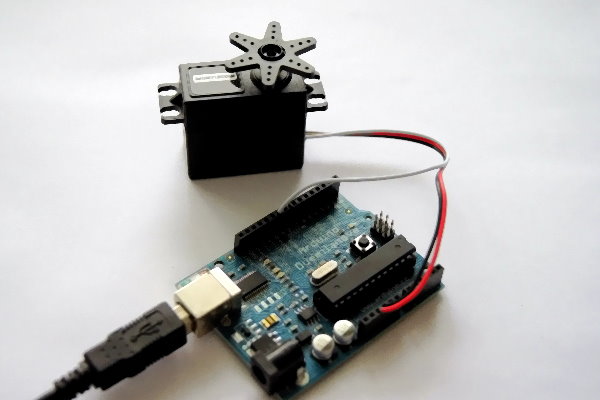
Since I can’t do without a model servo for a new project, I’d like to take the opportunity to write a little guide here on running model servos with the Arduino.
Basic theory
A servo consists of control electronics and a DC electric motor. Both units are packed into a very small space. The built-in electronics determine the rotation angle of the motor, for example by means of a potentiometer. The circuit then compares the servo’s input signal with the current position of the electric motor. That way the position of the motor can be regulated. For the model servo
used in the following setups, I use a PWM signal from the Arduino, where the width of the pulse corresponds to the input signal of the servo
. The frequency is usually 50 hertz, with a period of 20 ms. The pulse width of the input signal then ranges from 1 ms, which represents the left end stop of the servo
, to 2 ms for the right end stop of the servo
. So the center position is at about 1.5 ms. For the rest of the PWM period the signal stays LOW.
A bit of practice
The most common model servos have 3 connecting wires. These are usually assigned as follows:
- – GND (black)
- – PWM (white*, yellow, orange)
- – +5V (red)
* The servo used in my example
In the following I’ll show 2 ways of driving a servo from an Arduino. First I’ll show how to turn the theory described above into your own code. The second example uses the servo library that already ships with the Arduino IDE. The library saves the programmer from having to work out the correct pulse widths and frequencies.
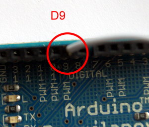
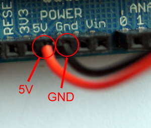
First the servo has to be wired up to the Arduino. The picture shows the correct wiring. The black wire of the servo goes to GND on the Arduino. The red wire of the servo
goes to 5V. And finally the wire that is white in my case goes to one of the PWM pins. To use the servo
library we pick pin 9 or pin 10, as shown in the picture, since these are already reserved for servo
operation.
Programming
The following code lets you run a servo without pulling in any libraries. This can be an advantage if you want to save space on the controller. Note that the following code uses pin 7 as the signal pin for the servo. So in this case the servo
should also be connected to pin 7.
Listing 1:
// Festlegen des Servo Pins

int servo = 7;


// Weitere Variablen für PWM und Drehwinkel (Position)

int pwm;

int pos;


/* Funktion um das Servo zu bewegen. Hier wird die Position

   berechnet und der Wert der neuen Position an das Servo

   übergeben.                                             */


void servoMove(int servo, int pos){

    //Winkel in Mikrosekunden umrechnen

    pwm = (pos * 11) + 500;

    // Servo Pin auf HIGH zum aktivieren des Servos

    digitalWrite(servo, HIGH);

    // Kurze Zeit warten

    delayMicroseconds(pwm);

    // Servo Pin auf LOW zum deaktivieren des servos

    digitalWrite(servo, LOW);

    // 20 ms warten

    delay(20);

}


// Initialisieren des Servo Pins

void setup() {

     pinMode(servo, OUTPUT);

}


// Hauptprogramm

void loop() {

  for(pos=0; pos<180; pos++) {
    servoMove(servo, pos);
  }
}
When the code runs, the servo moves once all the way to the end stop (180 degrees) and then turns back to the opposite end stop. After that the whole thing repeats.
Listing 2 shows a somewhat simpler solution. It relies on the servo library included in the Arduino IDE. The example can also be found in the IDE under File->Examples->Servo. I'd still like to list it here once more so the two methods can be compared directly. Note: Listing 2 uses pin 9.
Listing 2:
#include <Servo.h>

// Erzeugen eines Servo Objekts zur Servo Steuerung

Servo myservo;


// Variable zum Speichern der Position

int pos = 0;


// Initialisierung der Pins

void setup(){

    myservo.attach(9);

}

// Hauptprogramm

void loop(){

    for(pos = 0; pos < 180; pos++){
        myservo.write(pos);
        delay(15);
    }
}
Listing 2 moves the servo in the same way as Listing 1. The only difference between the two variants is the amount of code you have to write. So it's much easier and more convenient to use the servo library.
Finally, I'd like to briefly come back to the motor shield by Lady Ada that I've presented in a few other posts of mine. The shield can run 2 servos. Using the shield makes hooking up servos very easy, and on top of that it can run 2 steppers or 4 electric motors at the same time. Lady Ada's website has a detailed description of the shield and lots of code examples. So if you're looking for an easy way into robotics with the Arduino, I can only recommend the motor shield.
Comments