This article is long overdue, but better late than never. Hannover Messe is coming up, and with it the award ceremony for the current Make Light contest, in which I was able to defend my title once again. This year’s contest ran under the motto “Networked Photonics”.
Since I had a bit more time to prepare for the contest this time, I also submitted a bigger project, which I describe in more detail in this blog article.
I’d like to say thank you once again to everyone who voted for the project. I received an incredible number of more than 1000 votes. You can find all the details about the contest and my fellow competitors at:
https://www.photonik-campus.de/wettbewerbe/photonik-vernetzt-vernetzte-photonik/
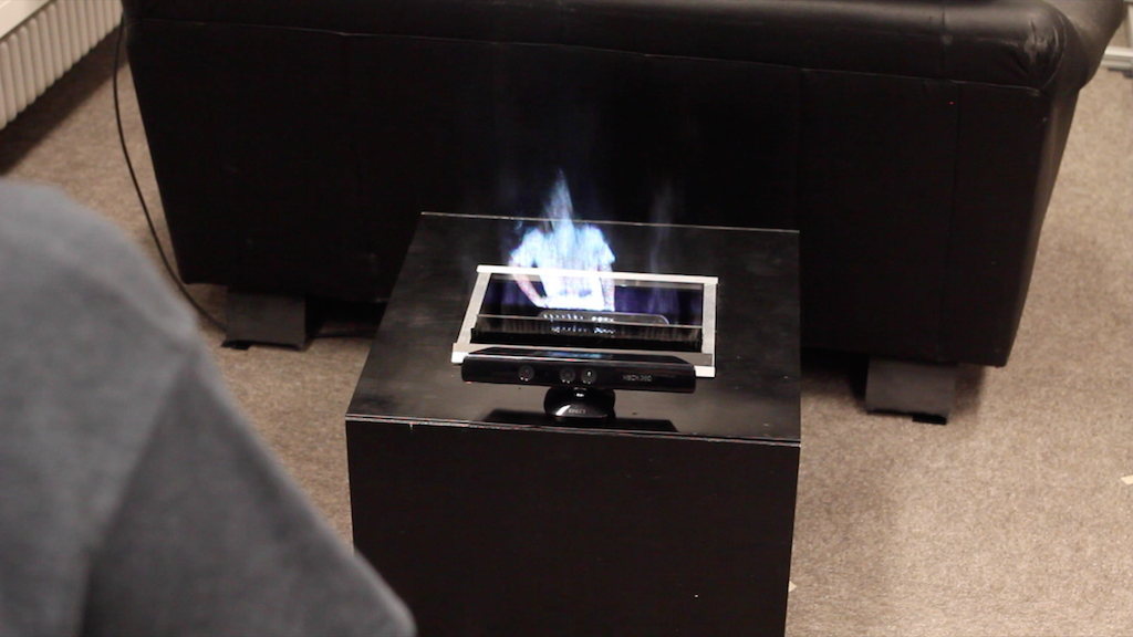
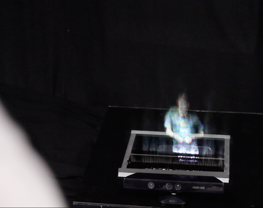
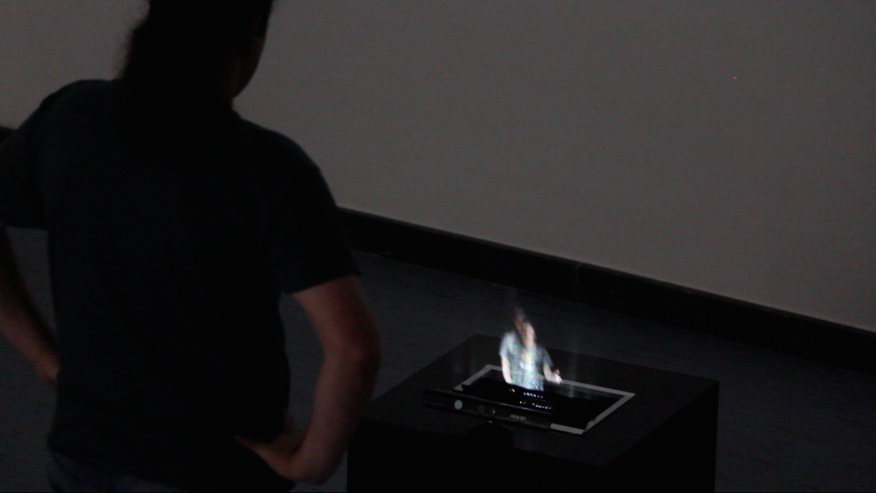
This year’s contest theme is certainly a bit harder. Lately I’ve been coming across more and more reports about “fog screens”. There are plenty of sites describing how to build one. With a “fog screen”, an image is projected onto fog, which results in a rather nice pseudo “holographic” effect.
Especially if you use videos or video streams with a black background for the projection.
For my project, however, I wanted to build in the projector so that it is as invisible as possible. The idea of the LUMICATOR was born. So I had to build a device that houses screen and projector at the same time, so that both remain more or less invisible to the viewer. And the whole thing was still supposed to stay as compact and portable as possible.
I won’t go into every detail below. I’ve written a PDF with exact build instructions. You can find this PDF on the Photonik Campus page.
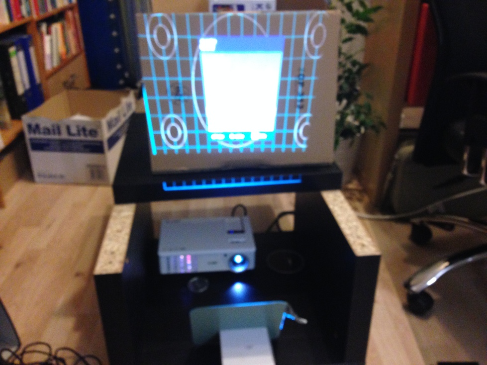
After a lot of trial and error, the choice fell on an IKEA table from the Lack series. I had already used this table for the “IKEA LED Arcade Table” project. So first I tested whether the dimensions would work for what I had in mind. To do that, I assembled half the table and put the projector inside. As the “wall of fog” I used a piece of cardboard.
To generate the fog I use, like many other projects, ultrasonic foggers made for indoor fountains. They can be bought cheaply on Ebay and Aliexpress. For the tank I used rigid PVC foam sheets. These are easy to cut with a craft knife as well as with a mini circular saw and are quite cheap at the hardware store.
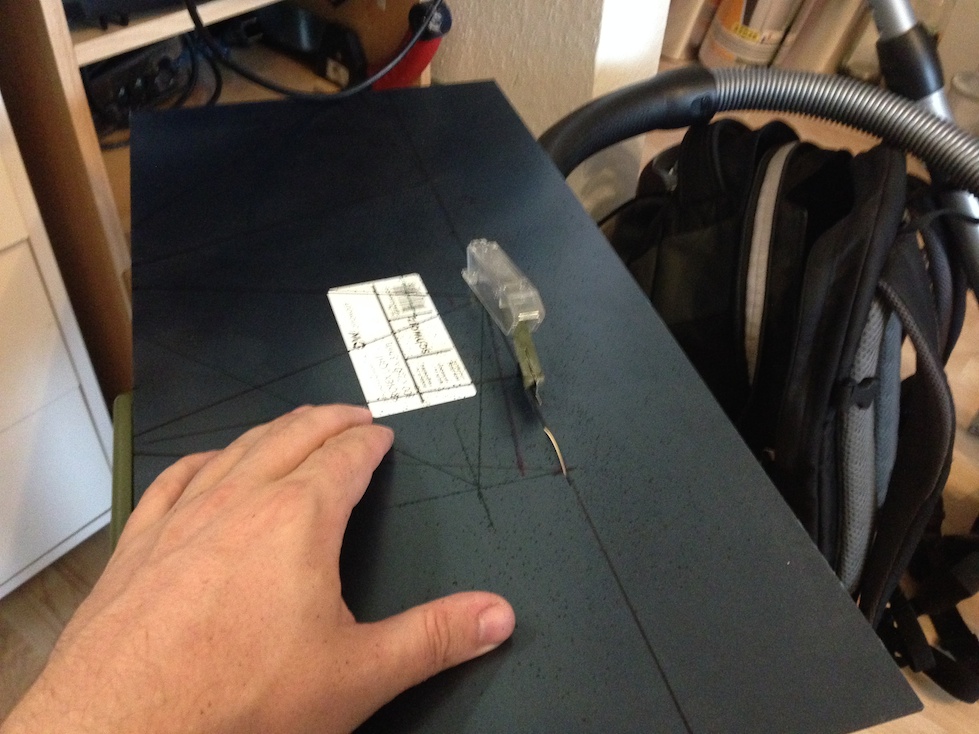
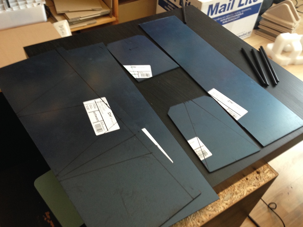
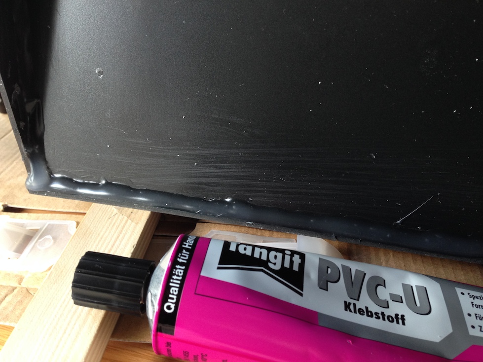
Once all the parts for the tank have been cut/sawn to size, the tank has to be glued together. Gluing turned out to be a tricky task, because the tank has to be absolutely watertight. After various glue experiments I settled on Tangit PVC adhesive. This adhesive is actually meant for PVC pipes, which is why you’ll find it in the plumbing section of any hardware store.
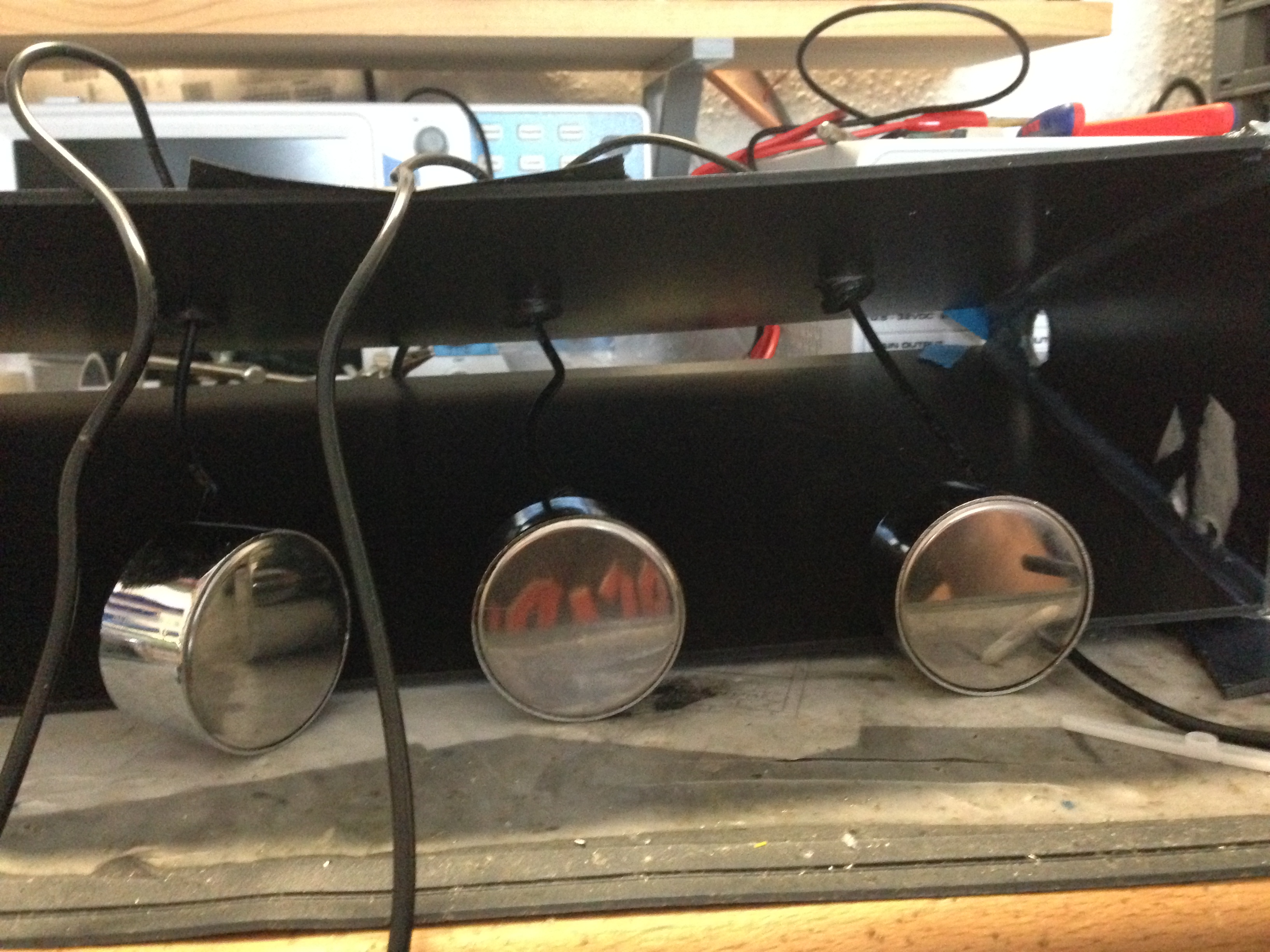 Before gluing the bottom onto the tank, you should drill holes in one of the side walls for the cables of the ultrasonic foggers. Then the foggers are mounted in the tank as shown in the photo on the right. Once everything is glued, you test whether the tank is watertight. Ideally in the bathtub or shower. Simply put a piece of kitchen roll under the tank and fill it with water. The paper towels should not have become damp even after a longer wait (ideally an hour or more).
Now air ducts have to be attached to the tank. One at the front and a second one at the back. To do this, cut suitable parts out of cardboard as shown in the pictures. And tape them to the tank.
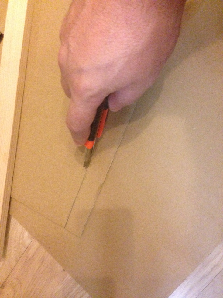
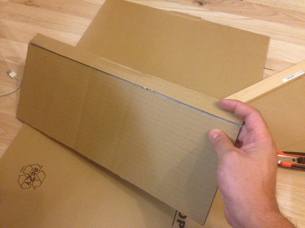
Before the two “wing” parts go onto the tank, PC case fans should be glued in. They are needed to generate the airflow.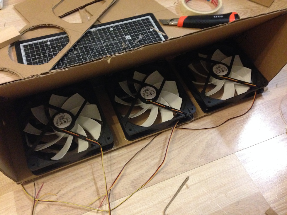 The finished tank with all its parts should then look like the following picture. To protect the cardboard walls a little from splashing water, I also covered them with tape. Alternatively, the side parts can of course be made from rigid PVC foam instead of cardboard. For lack of time, however, I skipped that.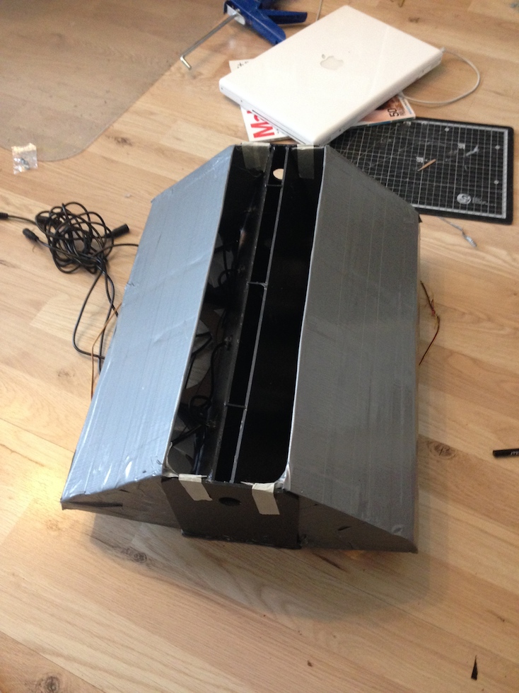
INFO: The construction of the side wings has since been completely reworked and made fit for Hannover Messe. All the cardboard parts have also been replaced with rigid PVC foam sheets.
Now for the tedious part. A whole lot of drinking straws have to be cut to the right length and glued together. These straws are glued in a kind of honeycomb pattern and will later shape the airflow. To cut the straws to length I made myself a suitable tool on the 3D printer. But you can also simply take a block of wood and drill 5 cm deep holes into it.
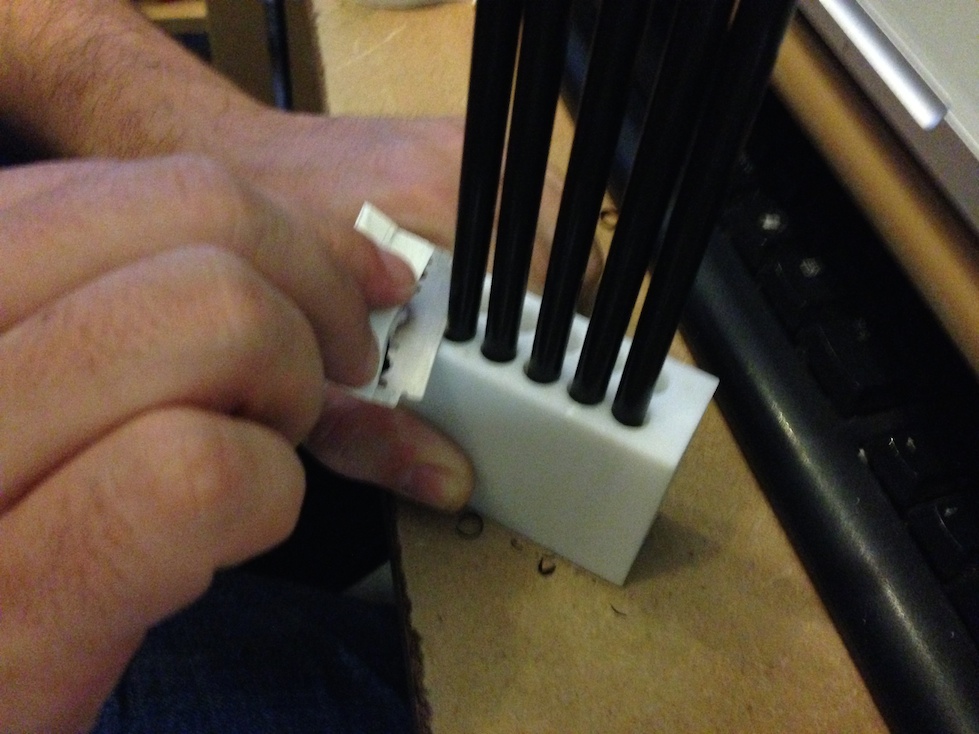
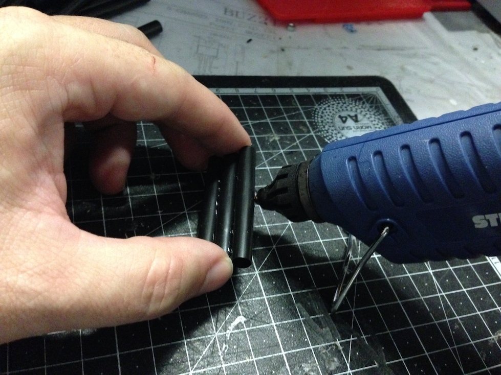
The straws came from a special offer at Aldi. For the project I cut up about 2 packs of these straws and collected the pieces in a bucket. After that I glued the straw pieces into rows with hot glue. So that the glue seams don’t look so ugly, I went with black hot glue. The straws should all end flush, and for that it helps to line them up against a wooden batten while gluing.
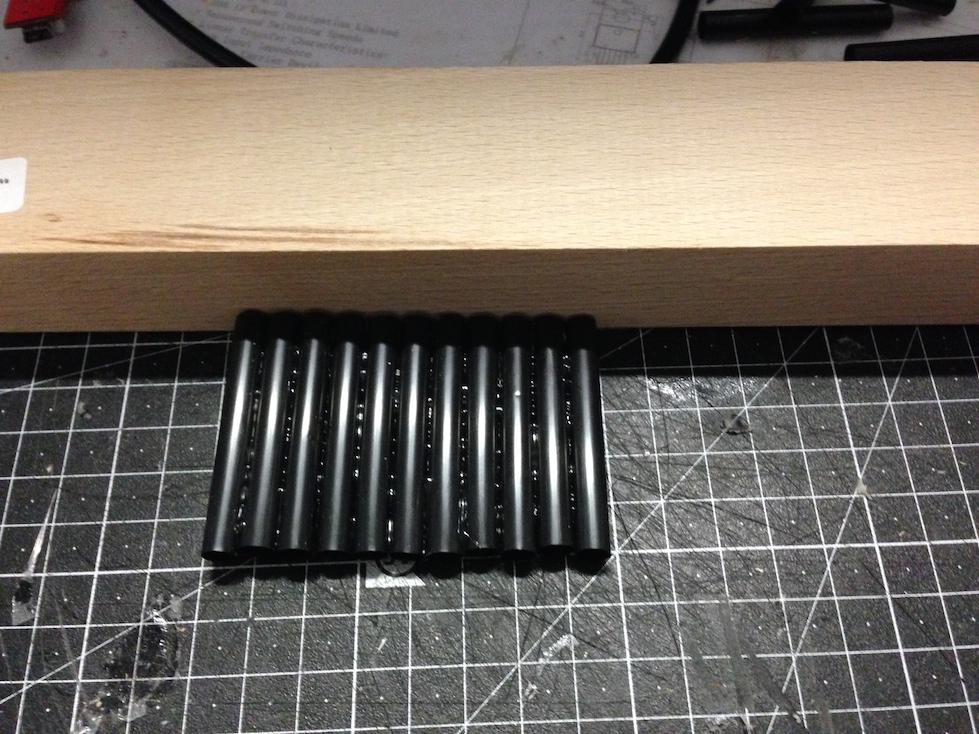
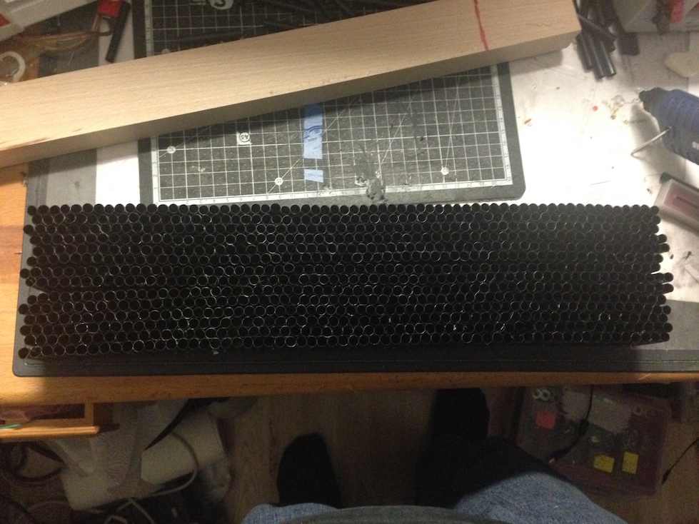
You need 2×8 rows. These are glued together into two blocks of honeycomb-shaped straws. That completes the air ducts as well. What’s still missing is a row for the fog to flow through. For this, one more row of straws is glued together. This row is framed with strips of rigid PVC foam.
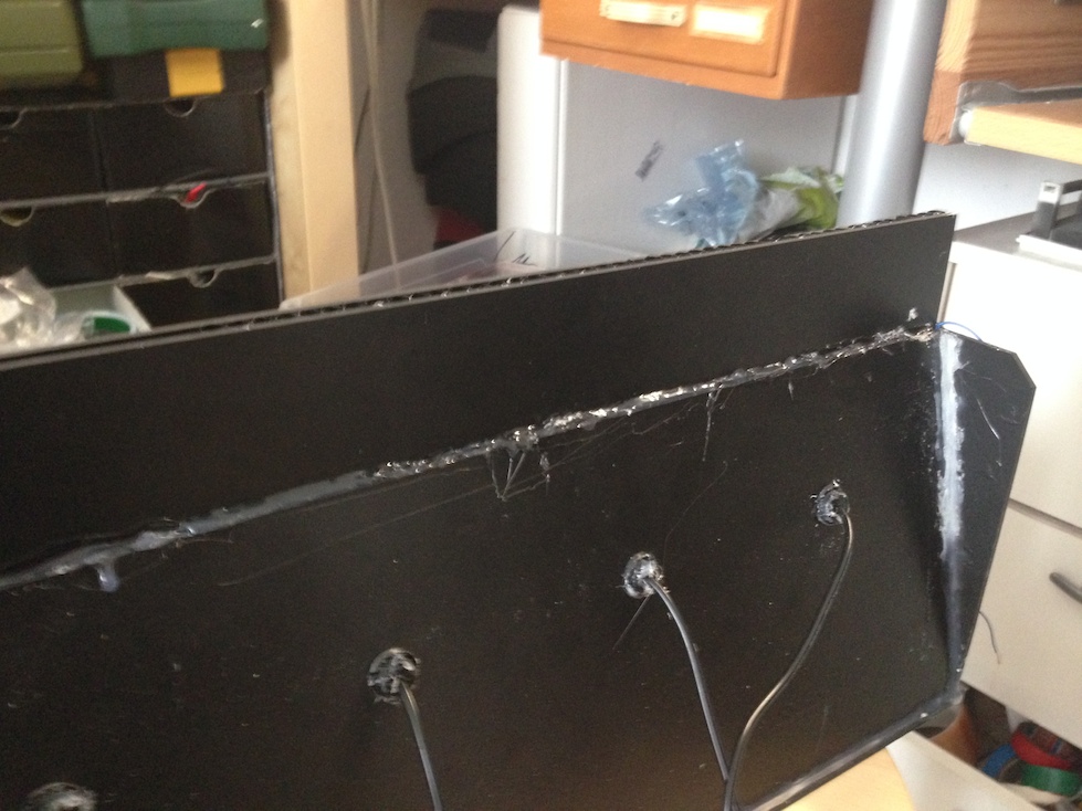
This row of straws is attached to the upper end of the tank. It’s best to glue it on one side only, so that the other side can still be opened. The remaining straw honeycombs are glued onto the two sides of the tank.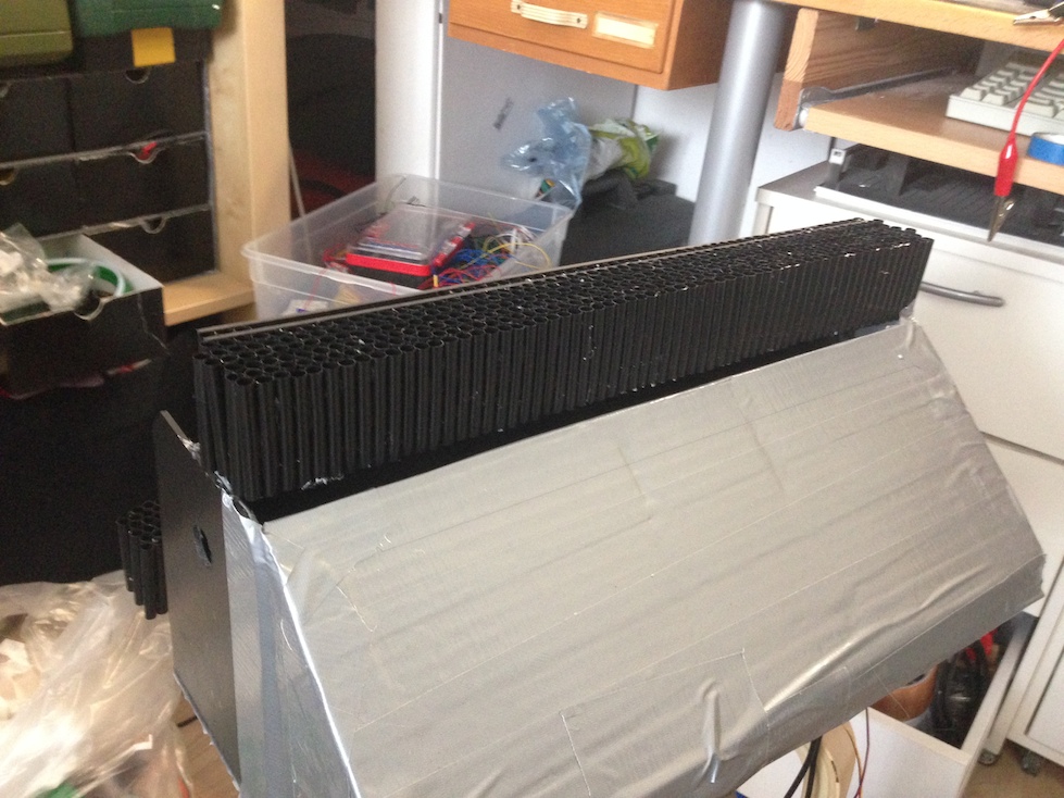
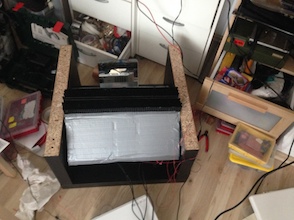
The finished tank is mounted in the Ikea table with brackets. The tests on the projection surface carried out at the beginning gave me the dimensions for the opening in the table top. These are transferred to the top. With the help of a Dremel and a Japanese saw, the matching cutout is then made in the table top.
. 
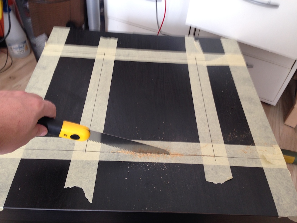
Detailed instructions on the best way to cut the opening into the table can be found in the article about the LED tables that I built with Christoph for Maker Faire Hannover last year.
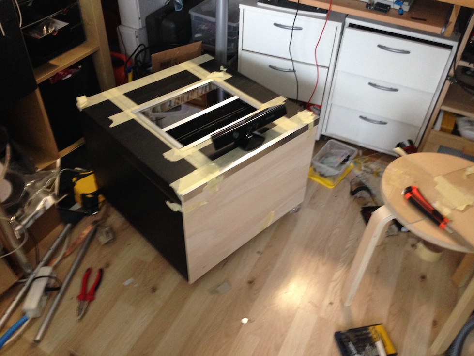
Finally, everything can be placed inside the table. The projector sits underneath the water tank and points at the rear wall of the table. On the rear wall of the table there is a mirror, tilted at just the right angle so that the projector’s image lands exactly on what will later be the wall of fog. For power, a power strip, a 24V AC power supply for the foggers and a 12V power supply for the fans are installed inside the table. A wooden panel from the hardware store was fitted to both the front and the back. These are held magnetically on metal brackets, so they can be taken off at any time and you can easily get at the inside of the table.
After painting the panels and switching it on for the first time, the projector’s startup logo was beaming at me.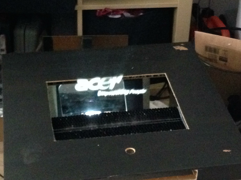
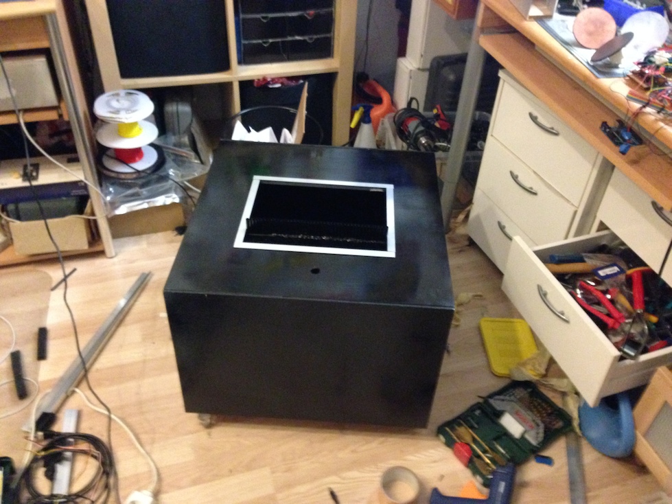
With a few simple steps and some aluminium strips, the table finally got a bit of a visual upgrade.
The first long-term test took place last year at the Maker Faire in Kerkrade. There the table ran for two whole days. For these trials I used a few Processing programs.
In the meantime, a Raspberry Pi2 has been installed as its heart. It now serves as the player for videos and interactive Kinect gimmicks. Unfortunately I won’t have enough time in the coming months to make many changes to the software.
I’ll most likely bring the table along to the Maker Faire in Hannover as well. So stay tuned.
Comments