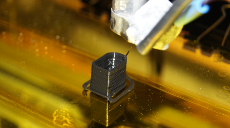
In the last part I briefly covered the electronics I’m using. In this part I’ll explain more details about the electronics and present the first print results. As you can already tell from this article’s cover picture, the project is getting close to “completion”.
Changes to the build
As in the last printer article, this time too we start with the most important modifications. A lot has changed on the print head. First, I replaced the Wade extruder with Greg’s Wade extruder
. Compared to the Wade extruder, Greg’s extruder comes with a few design improvements. For example, Greg’s extruder can easily be opened from the side by loosening just two screws. This mechanism makes cleaning the extruder so much easier, since every now and then filament dust does get left behind in the drive bolt (hobbed bolt). This dust can lead to poor print results.
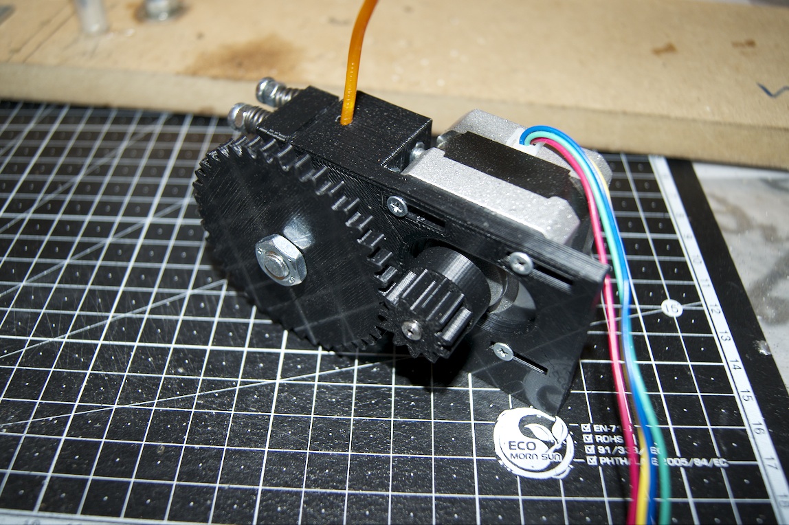
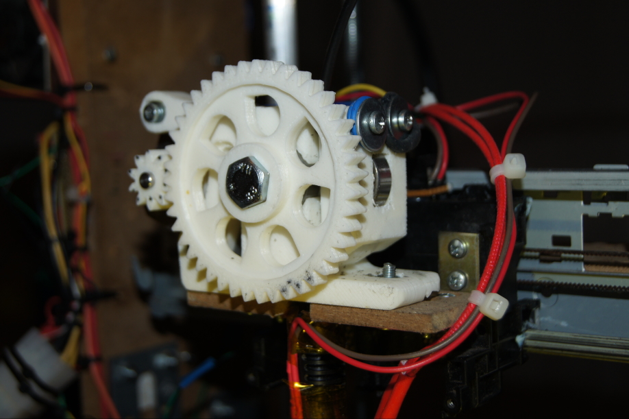
The left picture shows the Wade extruder and the right picture the much slimmer Greg’s Wade extruder
.
The next change on the print head is the hotend. Unfortunately, I never really got along with the arcol hotend. The biggest problem was the uneven filament feed rate. Again and again the extruder got stuck. It’s also possible that I damaged the hotend while trying to screw on a new nozzle. In the end I went for the cheaper J-Head MK-IV hotend with a 0.3 mm nozzle. So far the hotend has been working flawlessly. A huge advantage of this hotend is that you can buy it fully assembled for under 40 euros on eBay or in various online shops. That can save you a lot of fiddling with delicate parts.
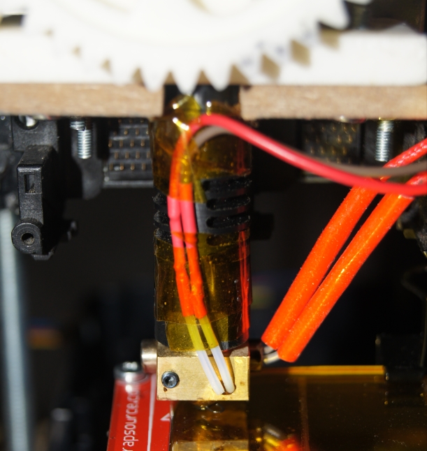
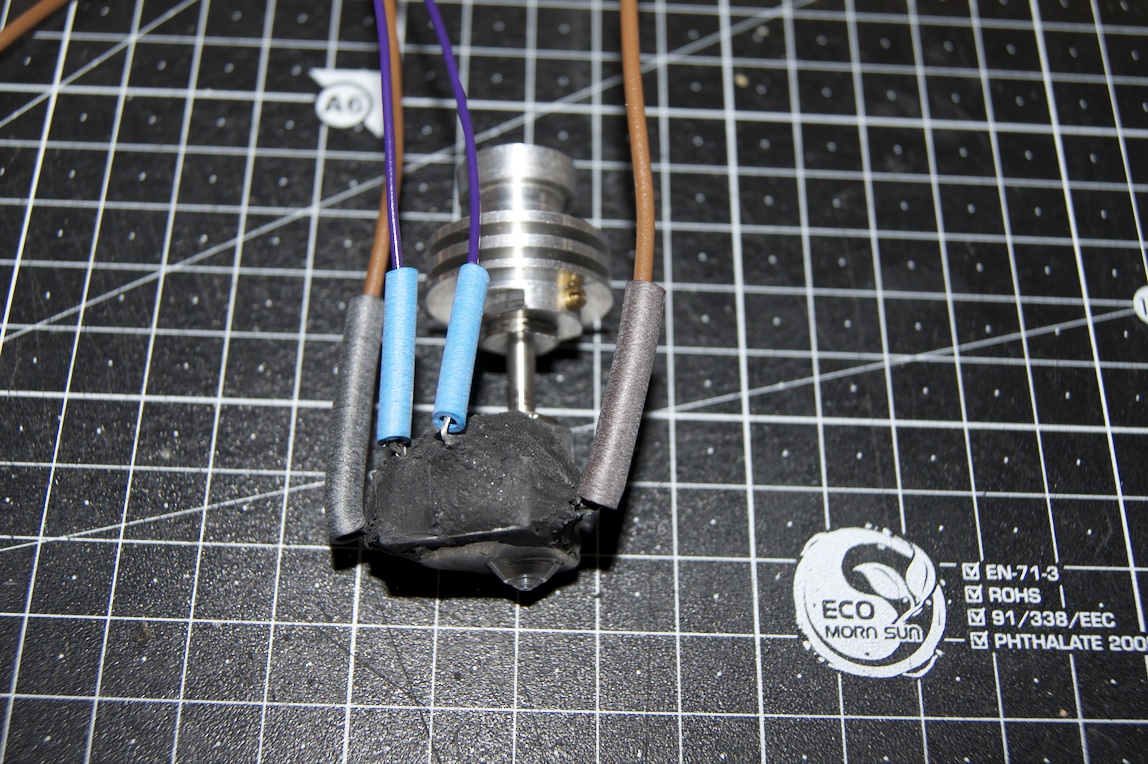
Here you can see the current J-Head hotend on the left and the previously used arcol hotend on the right. The J-Head also looks a bit cleaner in its workmanship, because the heater and temperature sensor aren’t attached with heat-resistant cement (the black lump on the arcol hotend) but can be fixed with clamping screws, which doesn’t seem to affect how it works, though.
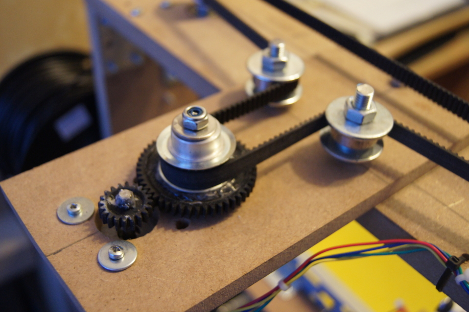
Another change was made to the belt drive of the Z axis. Since steps were frequently being lost in the Z direction during operation, it was clear there could only be two reasons. Either the mechanism doesn’t run smoothly enough or the motor is too weak. To save myself the effort of building a new Z axis, I tried to give the drive a bit more power. To do that, I built a gear reduction between the motor and the drive belt. The following picture shows the new, working construction. Since then there have been no problems with lost steps on the Z axis. Of course, all of this also depends on the motor speed. But the maximum speed can be set in the firmware. It can help to simply play around with different speeds to find the perfect setting.
What’s new in this part
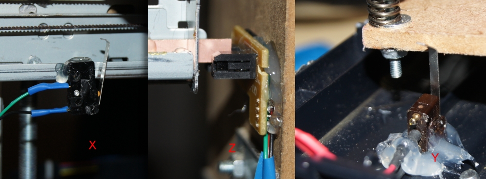
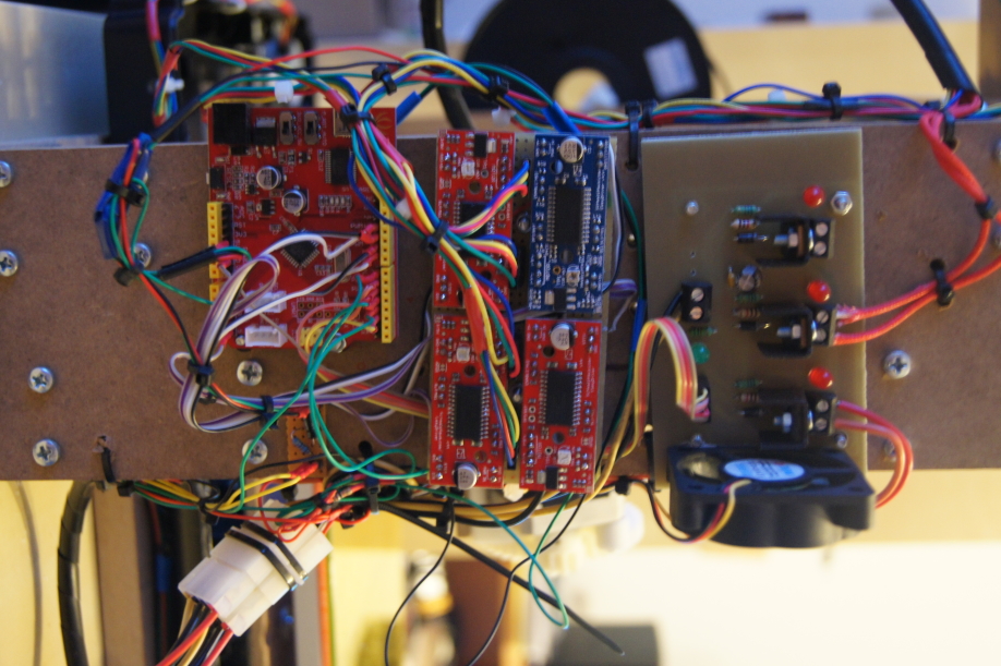
The biggest new thing so far is the wiring of the electronics. I already described the components used in the last part. Nothing has changed there. Only the Easy Drivers were soldered onto a perfboard and fitted with pin headers, which makes the wiring cleaner and simpler. The problem with the drivers burning out has been solved as well. The damage was caused by faulty wiring. I also added 3 endstops, for the X axis minimum position, the Y axis minimum position and the Z axis minimum position. All of the endstops were taken from old printers. The endstops for the X and Y axes are mechanical, and for the Z axis an optical endstop was used. The wiring and electronics for endstops are described very well in the RepRap wiki.
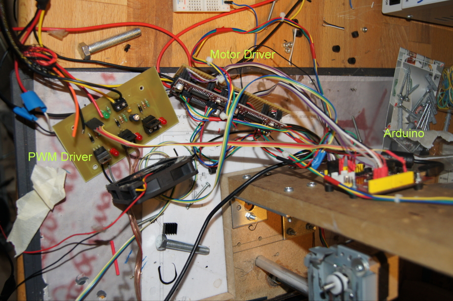
With the 4 motor drivers, the endstops, the connections for hotend and heated bed, and the temperature sensors, the Arduino is occupied down to the very last pin. The following picture shows the wiring of the first attempts. Once I was sure that everything worked well, I rewired it all properly.
I’m planning two Arduino shield add-ons to make it easy to replicate this printer or a similar one. One shield is meant to hold four Pololu motor drivers and is therefore suitable for other CNC projects as well. For this shield I’m deliberately going with the Pololu
drivers, because they are smaller and therefore fit better on a shield. This won’t change anything about the function, the wiring or the price. The second shield will then be the PWM driver for the heating and will also get screw terminals for the sensors and endstops. If you’re interested, please leave a comment so I can estimate how many boards to have made.
Since I’m using a small Arduino
UNO, Duemilanove or a compatible Arduino clone (the Seeeduino in my case). The firmware comes with a file called config.h. All you have to do is make the hardware-related settings there and then upload it to the controller with the Arduino IDE. The config.h for my printer can be downloaded from the download section of my blog. As host software I use Pronterface. With Pronterface you can move the axes manually or feed the printer with g-code. A detailed description of the software would go beyond the scope of this article. I’ll write a separate article about the software.
To be able to calibrate the print bed better, I also slightly modified the print bed construction. The print bed is now mounted on springs. This makes it possible to adjust the height of the print bed in order to get it evenly leveled. Calibrating the print bed correctly is very important, because otherwise the individual layers may not be printed evenly. This can, for example, cause the print to come loose from the print bed during printing (warping effect).
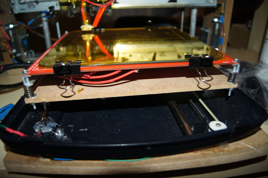
Since the heatbed isn’t one hundred percent flat and sometimes bows slightly when heated, it’s not advisable to print directly onto the heatbed
. Glass or metal plates are better suited. Since neither is exactly cheap, there is a budget solution here too, namely the good old IKEA mirror tile. The IKEA mirror tile already has the right dimensions and fits exactly onto the heated bed. The whole thing is clamped to the heated bed with binder clips from the office supplies. So far the tiles have withstood the temperatures well. To improve the adhesion of the print, I also covered the tile with Kapton tape

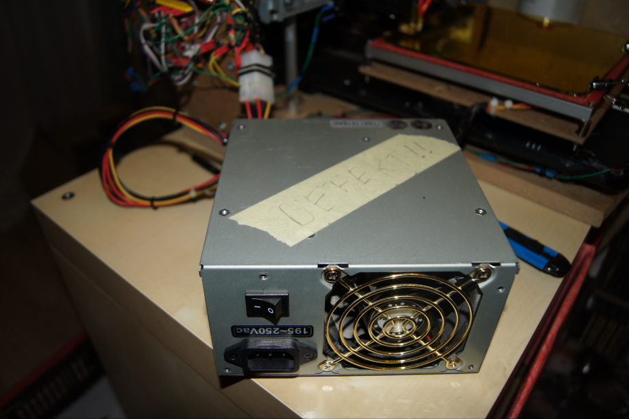
An old ATX power supply is used to power everything. The power supply delivers 12 volts for the motors, the hotend and the print bed, as well as 5 volts operating voltage for the sensors and electronics. It’s perhaps worth noting here that PC power supplies were not made for building 3D printers! So it could happen that the thing goes up in smoke on you. Be careful!
The following pictures give a little preview of the next article. There I’ll describe my current tinkering on the machine. The next article covers the calibration of the printer and the exact settings of the firmware and host software. The pictures show the first print attempts.
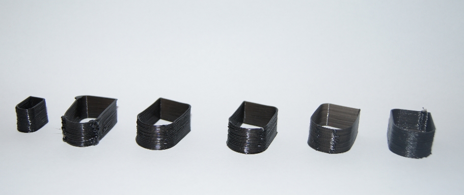
Here a thin wall test file was printed. From left to right you can see the results from the first print to one of the last. For the piece on the left, the axis settings weren’t right yet, which is why it is much smaller than the others. Around the middle attempt you can see that the layers get noticeably thinner; that’s where I switched to the J-Head with the smaller nozzle.
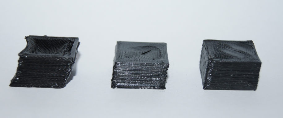
The following picture shows the 20×20 mm box print. Here, too, I still have some small problems. Again from left to right, from the first attempt to one of the last attempts. You can clearly see that the layers are still shifting. At first I thought it was a mechanical problem. Since the thin wall prints don’t show any shifting, I assume that the motors are losing steps. One possible reason for that could be motor drivers running too hot. Alternatively, I also wanted to turn the trim pots on the drivers. Hopefully I’ll have the problem under control by the next article. A video is overdue.
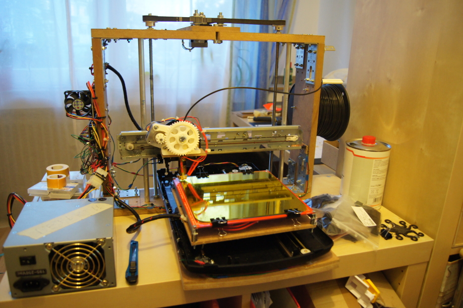
Last but not least, here’s a complete photo of the current version once more. I’ll try to write the next article faster, because that’s when things get really interesting. All that’s left to say: Keep on reading!
EDIT (April 24, 2013):
Here’s the video
Comments