In the previous part I described the mechanical build of the Z/X plane. In this part I’ll fill in the gaps in the mechanical build. Among other things, I’ll describe how I attached the extruder, hotend included, to the X carriage.
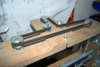
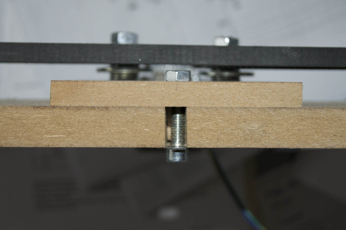
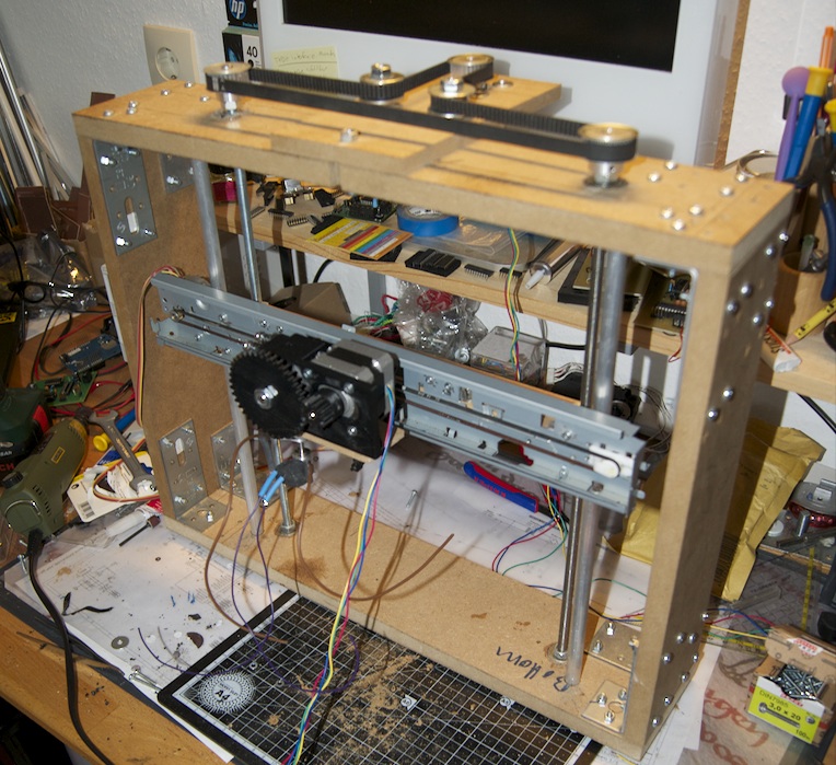
First I built the drive for the Z axis, which was still missing. Since I didn’t want to use 2 stepper motors for the threaded rods, I looked for a way to drive both threaded rods at the same time with a timing belt. I bought the timing belt and the matching pulleys on eBay. As I unfortunately didn’t have a suitable stepper motor from old printers at hand, a NEMA 17 stepper motor was used here. The timing belt is routed around a contraption of screws, washers and ball bearings to get the necessary tension (see picture). Thanks to three slots in the upper part of the frame, the motor mount can be shifted, so the timing belt can be loosened or tightened at any time.
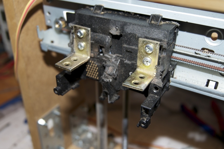
On the old cartridge carriage I first removed the surplus plastic with a Dremel and then attached two metal brackets using four M3 screws. I screwed the mounting plate for the hotend and the extruder to these brackets. Since the mounting plate supplied with the hotend was too small, I first had to make a new one. Compared to the supplied plate, the new plate is just a bit wider, which makes it easier to screw it to the brackets.
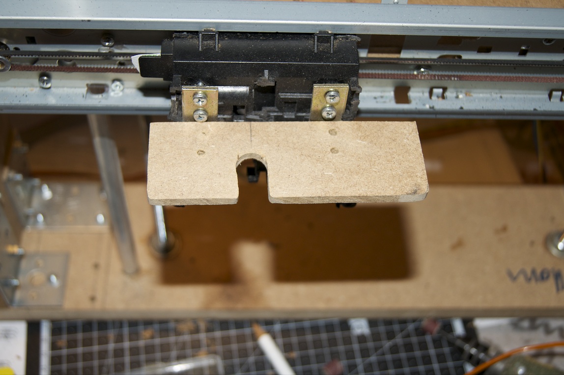
The following picture shows the new mounting plate in relation to the cartridge carriage with the brackets attached. I used 3mm MDF for the plate. For the hotend to fit exactly into the cutout intended for it, though, the plate needed a little more sanding.
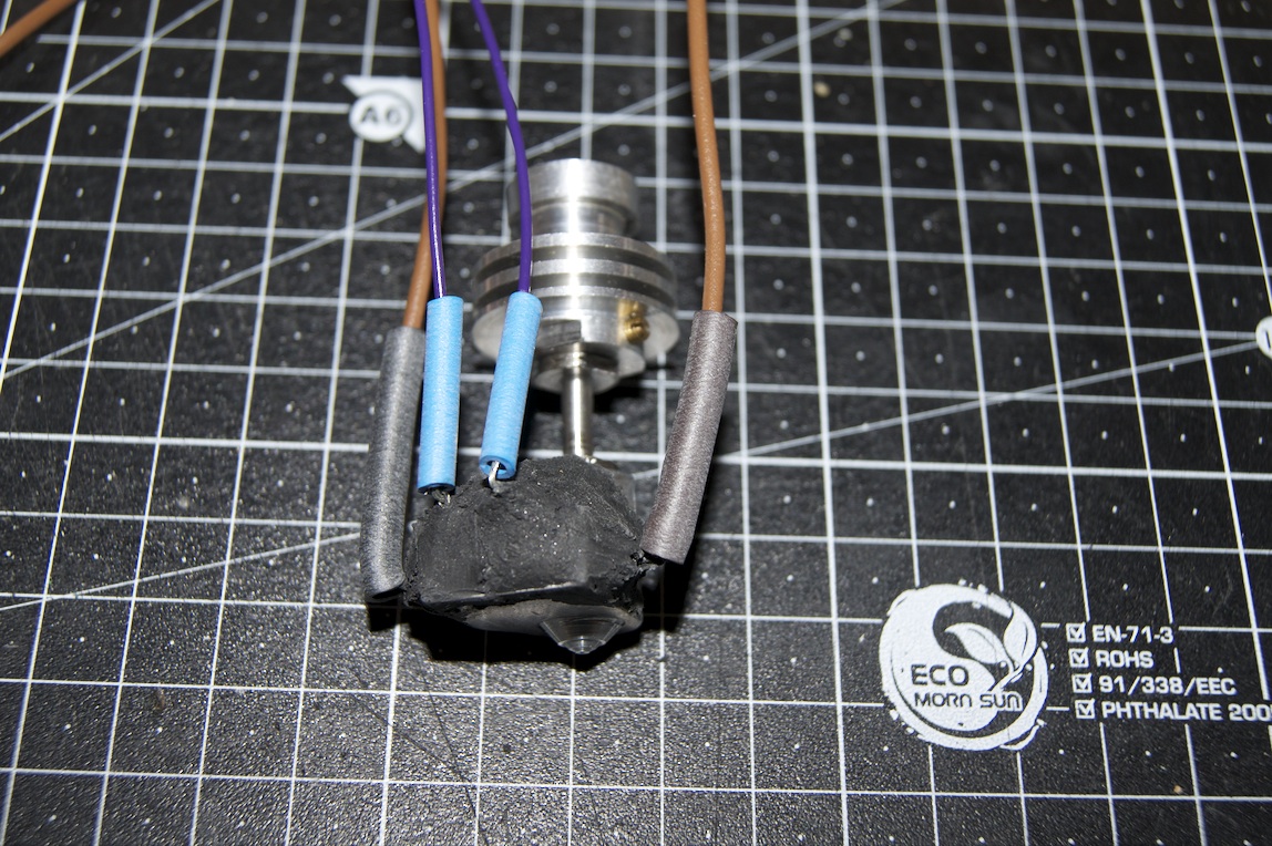
I’ll spare myself a detailed description of how to assemble the hotend and the Wade extruder here, since there are already plenty of write-ups on these topics online. If you’re interested in the assembly instructions for the Arcol hotend, have a look at the following wiki : https://wiki.arcol.hu/arcol-hu-hot-end-v4-assembly. Another short article on the hotend can be found at https://repraphd.blogspot.de/2012/05/review-arcolhu-v41.html. I bought the hotend kit on Ebay, but it can also be ordered directly from the manufacturer. The hotend I bought came with a 0.35mm nozzle, but I also bought an additional 0.5mm nozzle. I’ll probably do the first test prints with the 0.5mm nozzle. Alternatively, you can also find a different and possibly cheaper hotend
on Ebay
.
If you want to know more about assembling the Wade extruder, you can read up on it on the RepRap wiki pages. There you’ll find a very detailed article with videos and pictures explaining how the Wade extruder
is put together. I also bought my extruder from an Ebay seller.
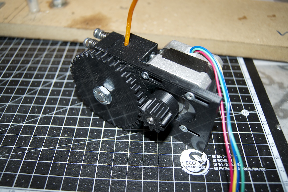
Once the individual parts were assembled, everything was fastened to the mounting plate. I had to take everything apart again and again to adjust the holes. The whole thing was extremely fiddly and took a great deal of patience. In the end, though, the whole assembly could be attached to the cartridge carriage of the X axis without any problems using the brackets. The result can be seen in the following picture.
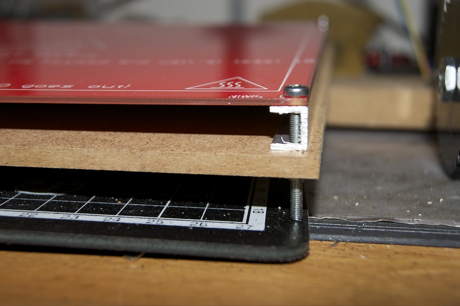
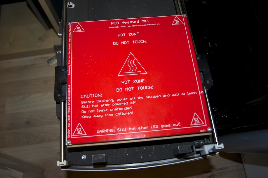
To finish the mechanical build, I also mounted the heatbed on the scanner. For this I used an aluminium profile and a 3mm MDF board. The board measures 210mm x 210mm and is thus cut to fit the heatbed
exactly. To attach the heatbed
, the two aluminium U-profiles from the hardware store were cut to a length of 210mm and holes were drilled in the appropriate places. The whole thing was then screwed together as shown in the photo and mounted on the scanner’s carriage.
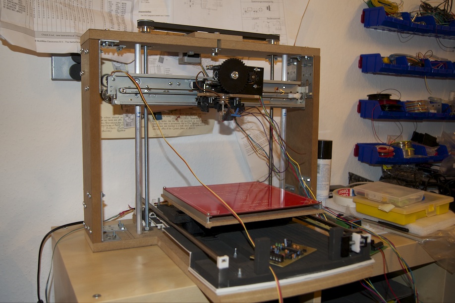
The finished build looks like the last picture. In the video I’m using one of the motor drivers I already made with the iModela. In the next part of this series I’ll describe the electronics I built.
Comments