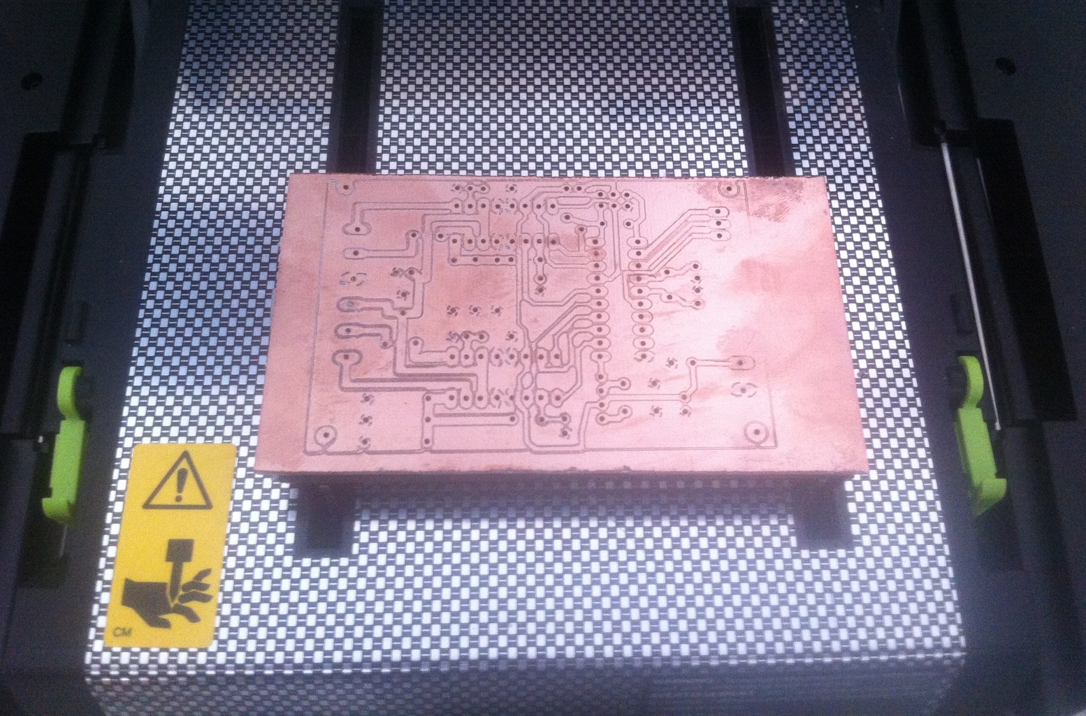
In the last part I described how to generate the milling data for the iModela with Eagle and prepare it for the milling process. In this part I’ll describe how to set up the iModela and then mill the PCB.
Preparing the iModela
First, you should stick a small sacrificial plate onto the table with double-sided tape to protect the table from accidental damage. As a sacrificial plate I use a foam-like craft plastic from the hardware store. Another layer of double-sided tape goes onto this plate, which will later hold the PCB blank.
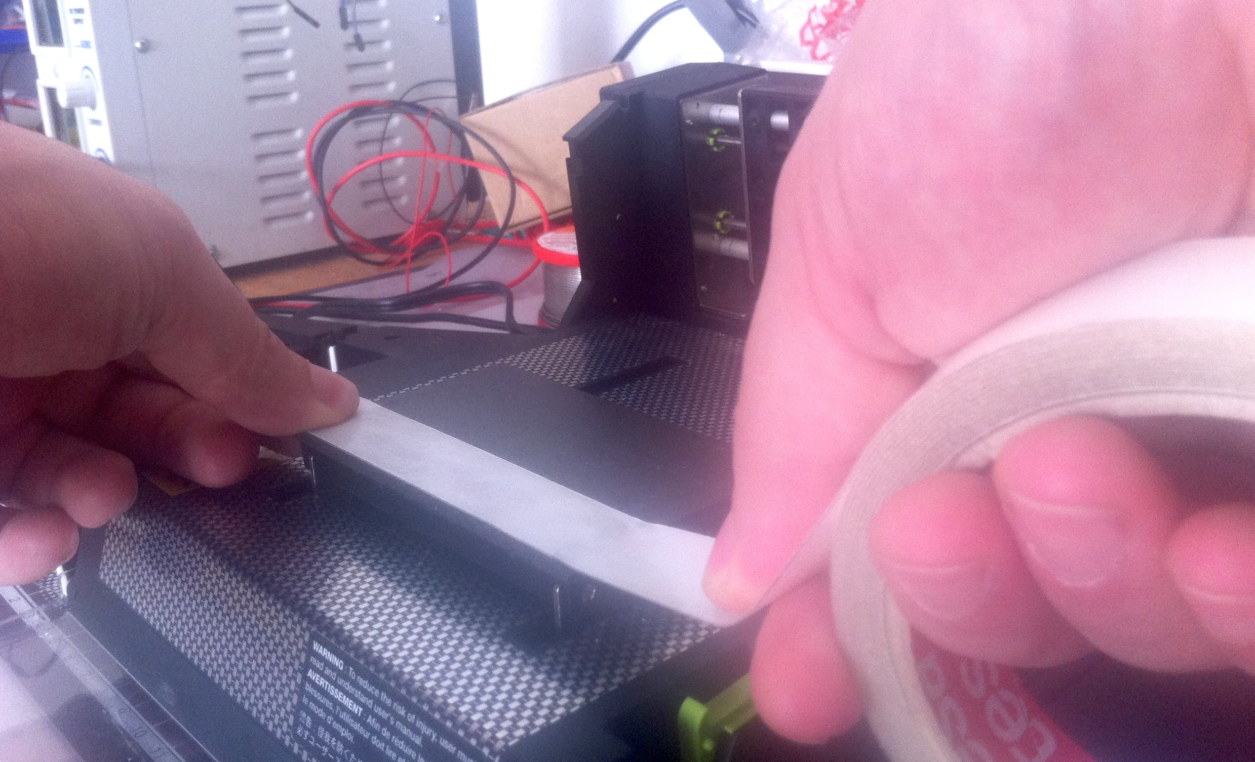
Then a PCB blank cut to size is stuck onto the table using the adhesive strips.

Milling tools
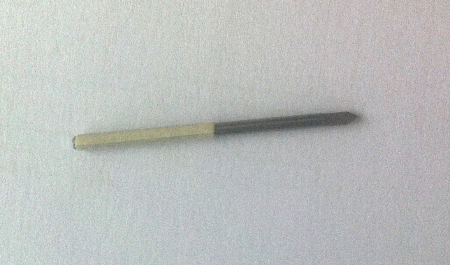
Since the iModela only accepts tools with a shank diameter of 2.3mm, it’s not that easy to find a suitable tool for milling PCBs. I tried various tools. First I tried my luck with an engraving tool from Proxxon (cutting diameter of 0.8mm). The result was very sobering. After that I tried to build an adapter for 1/8″ engraving bits. For this I used a shaft coupling from model ship building. However, the coupling caused too much imbalance and therefore led to a pretty useless result. After a long search on the internet I finally found an engraving bit with a shank diameter of 2mm on eBay. To make up for the missing 0.3mm, I built up the shank diameter with masking tape. With the tape, the bit sits nicely in the iModela’s collet and doesn’t wobble when the spindle is switched on. This bit gives quite good results; nevertheless, I’m going to have a collet for 1/8″ tools turned on a lathe soon.
For drilling the holes I use Proxxon drill bits in the sizes 0.5mm, 0.8mm and 1.2mm.
Calibrating the iModela
To calibrate the machine, the iModela Controller software has to be started.
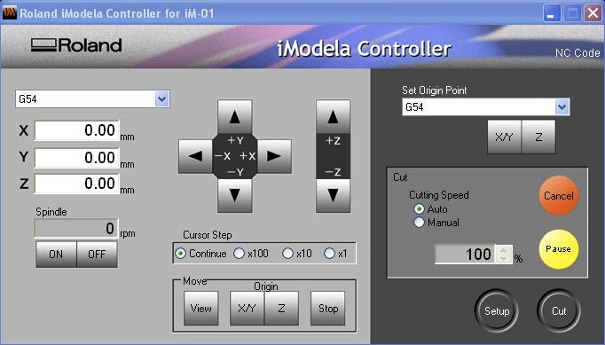
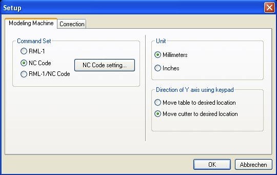
After starting it, the software has to be set to G-code input. You reach the settings dialog via the “Setup” button. There, the settings have to be made as shown in the picture.
Then the tool can be clamped in. To do this, the engraving bit is first loosely inserted into the collet. Next, you move the Z axis down until the bit just touches the PCB blank. Then the engraving bit is tightened with the supplied tool.
In the Controller software, the setting G54 is now selected in the combo box above the coordinate values. Then, under “Set Origin Point”, you can select the point G54 in the combo box on the right-hand side. To calibrate the Z axis, you now press Z below the combo box. The axis is now set to the zero point and can be raised a little.
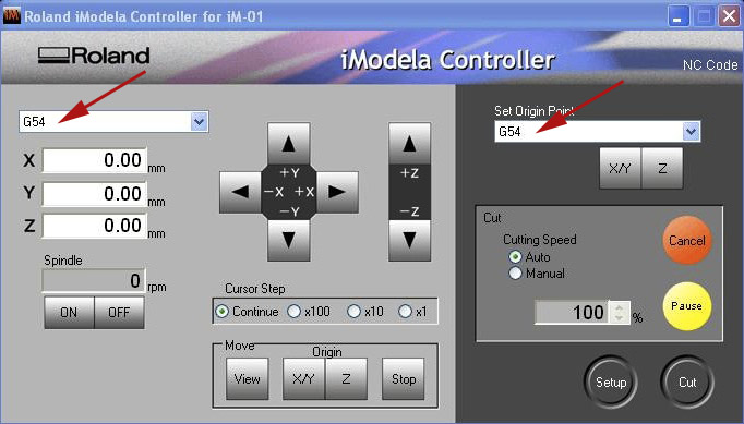
To calibrate the X and Y axes, you first move the axes to the workpiece zero point. If the G-code was generated with the Eagle ULP “pcb-gcode”, this is at the front right. Once the position is reached, you press the button labeled “X/Y”. With that, X and Y are calibrated as well.
Milling
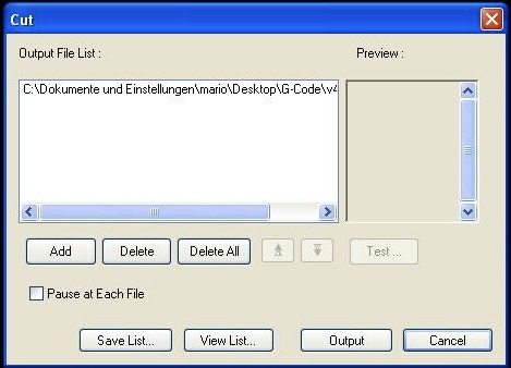
The machine is now prepared and the actual milling process can be started. To do this, click the button labeled “Cut” in the iModela software. In the dialog that appears, the milling files that were generated with Eagle can be loaded via the “Add” button. A click on the button labeled “Output” starts the milling process.
Drilling
To drill the holes, you proceed exactly as in the two previous steps. First the drill bit is clamped in. Make sure here that the X and Y axes are not recalibrated, because otherwise the drill holes will no longer line up with the milled traces. Only the Z axis has to be set to the zero point again after clamping in each drill bit. To move the X and Y axes to the zero point, click the button labeled “X/Y” in the Move field. Now the Z axis can be zeroed again with the drill bit, as described above. Once the machine is set up, the respective drill data is loaded in the file dialog, just like before, and the process is then started with “Output”. This step is carried out for each drill bit size.
Touching up
Unfortunately, it happens now and then that the milling wasn’t deep enough in some places. Such spots can be touched up with a utility knife, for example.
The following video shows the iModela in action during all of the steps.
Conclusion: The iModela is a great tool for quickly knocking out a single-layer PCB prototype. At the end of the video you can see the fully assembled board. It’s a motor driver that I’m going to use for my 3D printer project.
Comments