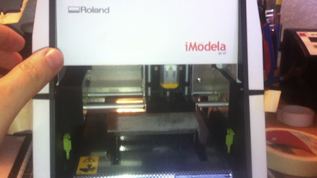
The iModela desktop milling machine, my prize from the c’t contest “Mach flott den Schrott”, arrived a few weeks ago. Since then I’ve been trying to make the controller boards for my 3D printer project with the mill. Since there are still very few hands-on reports on the subject of “milling PCBs with the Roland DG iModela mill”, I want to describe one possible approach here in a two-part series.
Preface
So far I’ve found only one hands-on report or guide on the subject. On the Arduino Blog I found a post in which Enrico Bassi (Fablab Torino) describes how to prepare PCB layouts for milling with the iModela using Fritzing and Inkscape. The graphics you create are loaded into the Roland DG software and then milled from there. The post describes the process step by step and comes with lots of detailed pictures. Since the iModela can also handle G-code, I looked for a way to generate the G-code directly with Eagle.
During my research I came across Christoph Selig’s website https://www.einfach-cnc.de/. Christoph Selig’s site is very informative and offers all sorts of interesting things about CNC milling. What particularly caught my eye, though, was the report on “milling PCBs”. Christoph Selig’s article gave me a lot of useful information on “milling PCBs with Eagle”. In this part I’ll mainly describe how to generate the milling data for the iModela from a schematic with Eagle. I won’t go into every detail. If you want more general information about milling PCBs, I recommend the website mentioned above.
Preparing Eagle
In the following description I assume a correctly installed Eagle Light Edition version 6.2.0 (available for free from CadSoft). First of all you need an extension, a so-called “ULP” (User Language Program), for generating the G-code. A suitable ULP for my case is called pcb-gcode. It can be downloaded for free, for example from the following link: https://pcbgcode.org/ The downloaded file then has to be unpacked into the directory C:\Program Files\EAGLE\ulp. Instructions for installing it on other systems can be found in the file docs/readme.html
I’ve created a matching pcb-gcode profile for the iModela. It can be downloaded from the download area of the blog. The file named imodela.pp then has to be copied into the directory C:\Program Files\EAGLE\ulp\profiles\.
Since I want to use this article to mill stepper drivers for my 3D printer project, I searched the web for a suitable board that can be made with the iModela. I finally struck gold on the site https://letsmakerobots.com/. There you’ll find a Github link to Tinhead’s motor drivers. The archive contains several versions; I went with version 4. I did have to modify the layout slightly, though, so that it fits the dimensions of the iModela. I’ll explain the technical details of the different driver versions in part 3 of the series 3D Printer from Computer Scrap.
Adjusting the design rules
Once all the preparations are done, we can get started. First open the board you want to mill. To get a good result, the “Design Rules” have to be adjusted accordingly. To do this, open the Design Rules dialog with the following command:
drc
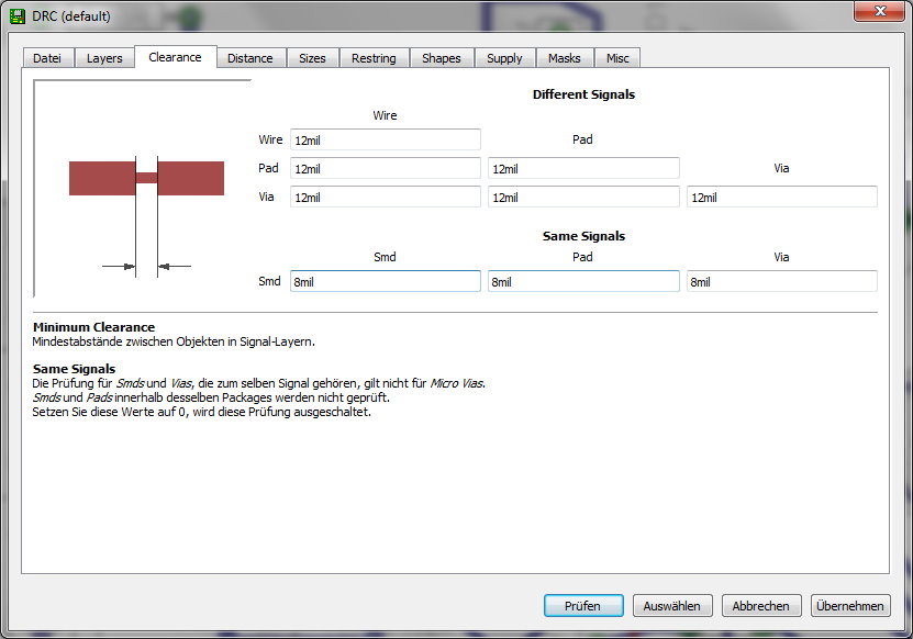
There, first select the “Clearance” tab to set the clearances to 12mil (0.30 mm). You can play around with the values here to get a good/better result.
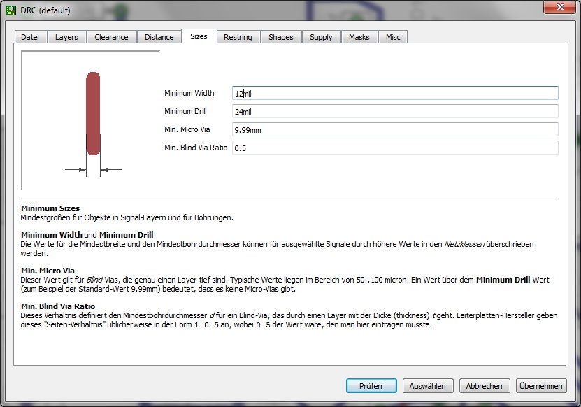
Next, select the “Sizes” tab. This is where the minimum width of the traces is set. Here, too, I started with a value of 12mil (0.30mm).
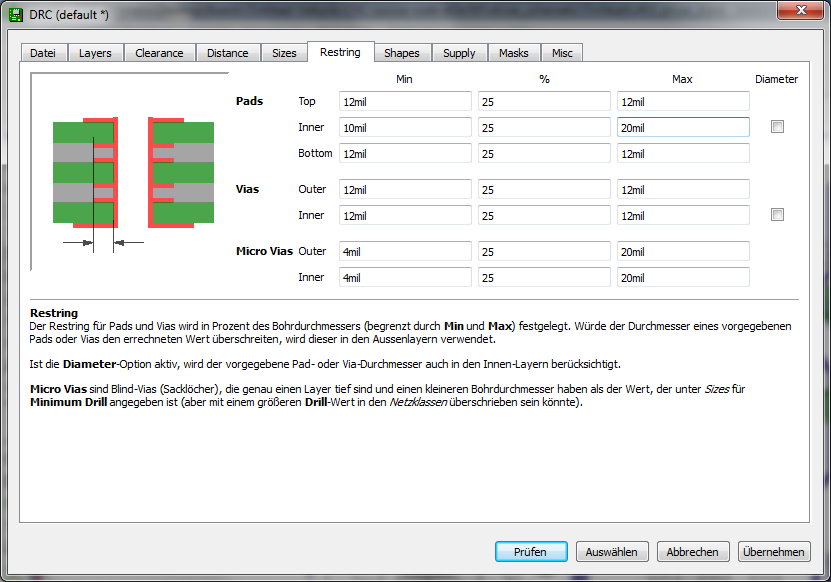
As the last setting, select the “Restring” tab. There I entered 12mil for the pads as well. After that you can close the dialog again by clicking Check. Most likely an error list will appear complaining about clearances that are too small. If necessary, you should rework the trace spacing here.
Generating the G-code
Now you can open the pcb-gcode settings dialog with the following command.
run pcb-gcode-setup
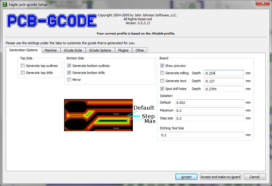
In the dialog that appears you can make settings relating to the machine. The values I used can be taken from the screenshots. Below I’ll explain in a few sentences the meaning of the parameters I changed.
- Generate Bottom:Makes sure the milling data for the bottom side of the PCB is generated.
- Generate Bottom Drills: Makes sure the data for the drill holes is generated.
- Show preview: With this setting, a milling preview is shown after the data has been generated. (Can be very useful later on)
- Isolation default:A small value should be chosen here.
- Isolation Maximum:This value specifies the maximum width of the isolation.
- Isolation Step size:This value specifies by how much the isolation is widened with each pass.
- Etching tool size:This value depends on the type of tool chosen.
To find the right value for the “Etching tool size”, you first need to know the angle of the engraving bit you’ve chosen. In my case the angle is 60°. In the next part of this series I’ll explain why I decided on an engraving bit of this kind. The width of the tool can now be calculated with the following formula:
Fräsbreite = Tangens(Winkel/2) * Frästiefe * 2 For the bit I chose, a milling depth of 0.19 mm ( a bit of experimenting is called for here ) results in a tool width of 0.2 mm.
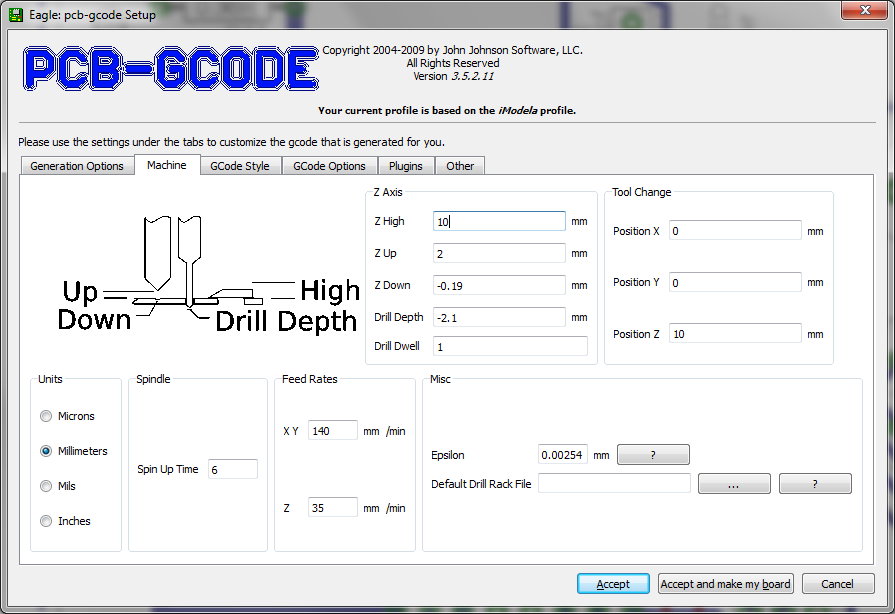
Next, click on the tab for the machine settings.
- Units: This is where the unit of measurement can be set. Careful, this setting converts the unit of measurement. So values you entered earlier may be converted as well.
- Spin up time:This value specifies how long to wait after the spindle has been switched on.
- Feed rate XY:This value specifies the feed rate for the X and Y axes; here, too, you can experiment.
- Feed rate Z:This value specifies the feed rate for the Z axis.
- Z High: This value specifies a height that avoids collisions with clamps. Since there is no clamping on the iModela, because the workpiece is fixed to the table with adhesive tape, you can choose any value here.
- Z Up:This value specifies how high the tool is lifted between each work step. It should be kept rather small to save time.
- Z Down:This value specifies how deep the isolation should be. Here, too, you can experiment with the values. I got my best result so far with the value shown.
- Drill Depth: This value specifies how deep the holes should be drilled. It depends on the thickness of the PCB.
- Drill Dwell: Specifies how long the drill bit dwells in the hole.
- Tool Change here you can specify a position that the machine moves to for changing the tool. Since on the iModela the drill bit is swapped at most once per drilling pass, this value can be chosen freely. It’s an advantage to choose the zero point here.
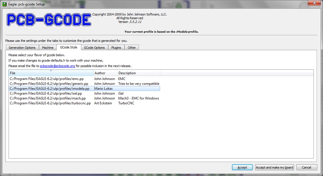
In the settings dialog for the G-code style, select the profile I created for the iModela mill. Once all the settings have been made, you can apply them by clicking “Accept and make my board”. A dialog follows asking whether you want to save the settings. You can confirm this dialog with “Yes”.
Now the G-code is generated and then the preview opens. The files containing the G-code are located in the Eagle project directory, where the schematic and board file also live. For milling with the iModela, it’s mainly the two files with the following names that are of interest.
projekt_name.bot.drill (Bohrdaten Bottom Layer)

projekt_name.bot.etch (Fräsdaten Bottom Layer)
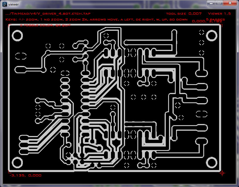
In the preview window you can see whether the milling data is okay so far. The white lines represent the milling paths. If everything is fine, you can go on to preparing the drill data. If you’re not yet happy with the result, you can tweak the parameters above until you get a satisfactory one.
Adjusting the drill data
The drill data for all drill bits is written to a single file. To make tool changes easier, I created a separate file for each drill bit. So that you don’t have to change drill bits all the time, it’s enough to group various drill sizes together. In total I created three files, for 0.5mm, 0.8mm and 1.0mm respectively. For this I made myself a template with the following content.
(Copyright 2005 - 2009 by John Johnson)

(See readme.txt for licensing terms.)

(This file generated from the board:)

(.../driver_schematic/TinHead/v4/V_driver_4.brd)

(Current profile is .../EAGLE-6.2/ulp/profiles/generic.pp  )

(This file generated 17.07.2012 00:27:25)

( Tool|       Size       |  Min Sub |  Max Sub |   Count )

( T01  0.610mm 0.0240in 0.0000in 0.0000in )

( T02  0.813mm 0.0320in 0.0000in 0.0000in )

( T03  0.900mm 0.0354in 0.0000in 0.0000in )

( T04  1.000mm 0.0394in 0.0000in 0.0000in )

( T05  1.016mm 0.0400in 0.0000in 0.0000in )

( T06  1.321mm 0.0520in 0.0000in 0.0000in )

( T07  2.200mm 0.0866in 0.0000in 0.0000in )

G21

(Absolute Coordinates)

G90

.... Bohrdaten hier einfügen ....

T01

G00 Z10.0000

M05

M02
In the file projekt_name.bot.drill you can recognize a drill change, for example, by the following lines:
M05

G00 Z10.0000

G00 X0.0000 Y0.0000

M06 T01  ; 0.6096
At such a point, a block with the coordinates follows, up to the next drill change. Copy such a block, including the lines shown above, into the template. Then save the file under a sensible name such as 5_mm_drill.nc. Repeat the process for all the drill sizes you want.
The G-code is now prepared for the iModela. In the next part I’ll describe how to use these files to make the PCB with the iModela desktop milling machine.
Comments