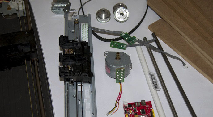
Since I recently managed to rescue a multifunction device (printer, scanner) from the bulky waste, it’s time once again to build something useful out of this retired hardware. As I urgently need a 3D printer, I’m going to try, in a multi-part article, to build a
Repstrap from old PC hardware and a bit of hardware store material.
Idea
The 3D printer is essentially going to consist of an old scanner and the linear guide from the multifunction device mentioned above, with the scanner serving as the Y axis and the linear guide from the printer as the X axis. The Z axis will be built with 2 x M8 threaded rods and a stepper motor, also taken from an old laser printer. Later on, an Arcol.hu Hotend 4.0 kit with a 0.35 mm bore will be added, which I’ve already ordered from 2printbeta.de. For the controller I’ll probably use an Arduino UNO. As always, the principle for this scrap project is: as cheap as possible!
Parts list
- 1 x multifunction device (bulky waste)
- 1 x scanner (bulky waste)
- 1 x stepper motor from a laser printer (bulky waste)
- 1 x stepper motor from an inkjet printer (bulky waste)
- 1 x Arcol.hu Hotend 4.0 kit with 0.35 mm bore ( 2printbeta.de)
- 1 x timing belt (Ebay)
- 4 x ball bearings (inline skates)
- assorted screws (hardware store)
- 4 x MDF boards, cut to size
- 1 x M8 threaded rod
The list is not complete yet and will be extended as the series goes on.
Removing and preparing the parts
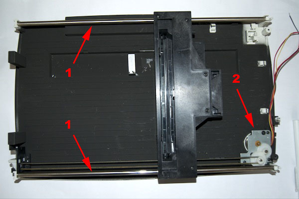
First, the required parts have to be removed from the old hardware. I started with the scanner and stripped it of all the housing and electronics parts that were no longer needed. The stepper motor stays in, of course. Unfortunately I no longer know exactly which scanner model I used. It seems to be a somewhat older model, though, as the mechanics are very sturdy. I’m sure this will work with a different scanner as well. You just have to make sure that the guide isn’t too cheap and therefore too wobbly. As you can see, on the model I used the linear guide consists of steel shafts on both sides.
Next I took the multifunction device apart to get at the cartridge carriage of the print unit. The device was a Canon MP 250. The linear guide consists of a sheet metal part on which the cartridge holder slides on a plain bearing. As with the scanner, it is driven by a timing belt. In almost all inkjet printers, however, the cartridge carriage is not moved by a stepper motor but by a DC motor with optical position sensing. So a stepper motor solution has to be cobbled together first. You could also use the DC motor with the optical position sensing, but that leads to considerably more programming work later on.
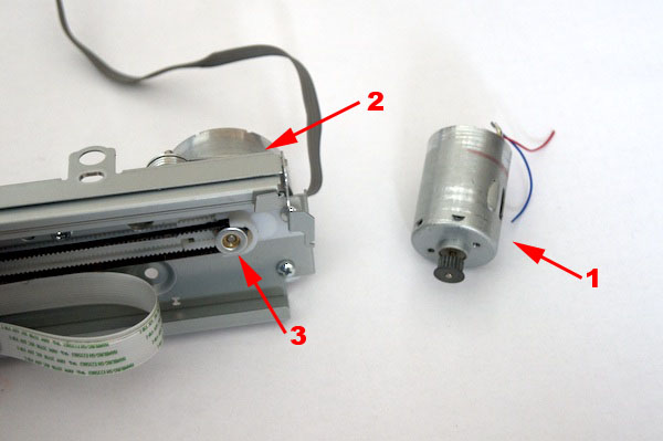
I removed the DC motor (1) and replaced it with a stepper motor (2) that I still had lying around. The new motor also comes from an inkjet printer, though there it was used for the paper feed. Luckily, the gear mounted on its shaft was an exact match for the timing belt of the Canon MP250. To keep the timing belt from jumping off the motor shaft, I also superglued a washer (3) centered onto the gear. I fastened the stepper motor with screws (M3) from the hardware store. The following picture shows the whole part once more with the stepper motor installed.
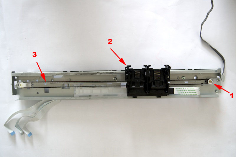
In the middle of the picture you can see the cartridge carriage (2). The extruder and the hotend will be attached to it later. I still have to come up with a suitable bracket or plate for mounting them.
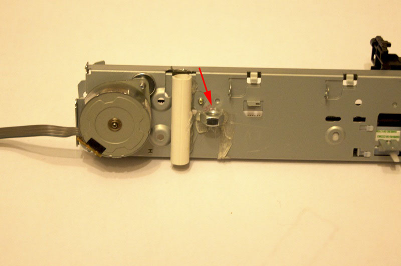
Finally, I glued 2 nuts (M8), one on the right and one on the left, to the back of the carrier using superglue and hot glue. Together with a threaded rod, the nuts will later provide the feed in the Z direction.
Testing the prepared parts
The video shows a test of the two parts I presented in this article. To test the motors I’m once again using, as in other articles, the Motor Shield by Lady Ada.
In the next part I’ll describe how the parts from this article are put together.
Comments