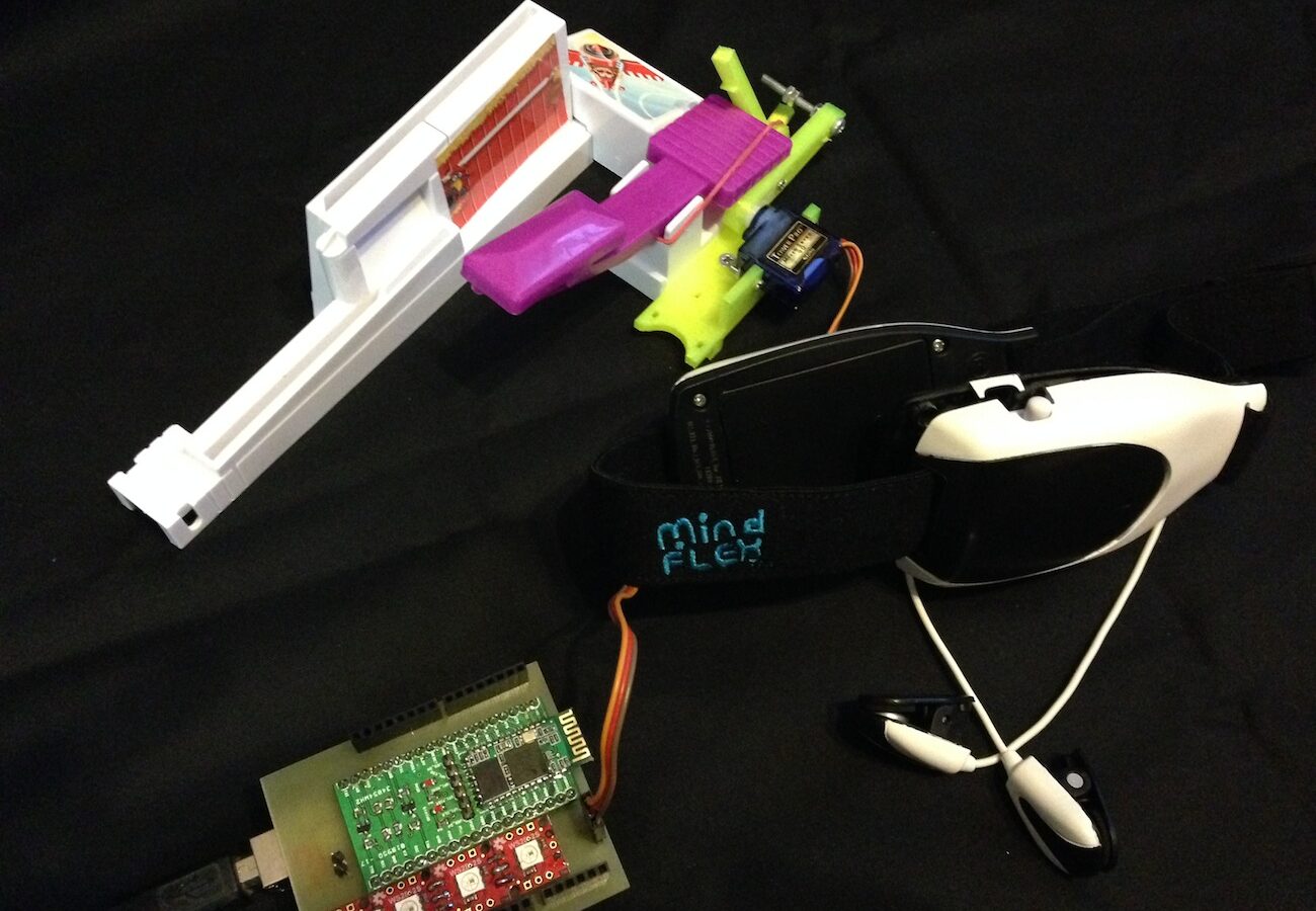
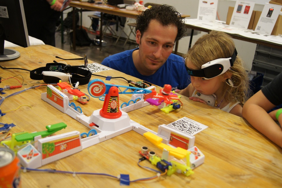
A few weeks ago I presented my Maker Faire project in Kerkrade. It was a new Looping Louie hack.
This project actually consists of two sub-projects: the Looping Louie Mind Controller on the one hand and my Looping Louie Autopilot on the other. In this article I’ll focus on the Mind Controller. The Autopilot gets an article of its own, since I’d like to offer it as a kit in my shop. To everyone already waiting for the eight-player Louie adapter: it too will show up in the shop around Christmas at the latest.
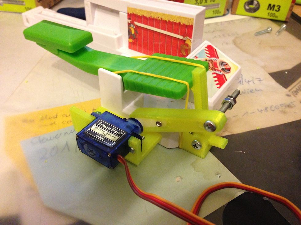
As mentioned above, the Mind Flex controlled Looping Louie is based on my Autopilot mechanism. This is a small hobby servo that operates the paddle arm by way of an ultrasonic sensor and a small controller board. The arm is preloaded with a rubber band. The servo releases the arm and then tensions the rubber band again. All the mounts come out of the 3D printer.
The idea now is to trigger the servo with your thoughts. I was inspired by a promotional video I saw on Youtube some time ago.
After a bit of research on the web I eventually found the game Mind Flex. You can get it on eBay for just a few euros. On top of that, there was already a hack and the matching Arduino libraries. The Frontier Nerds blog has a guide on how to get at the headset’s data.
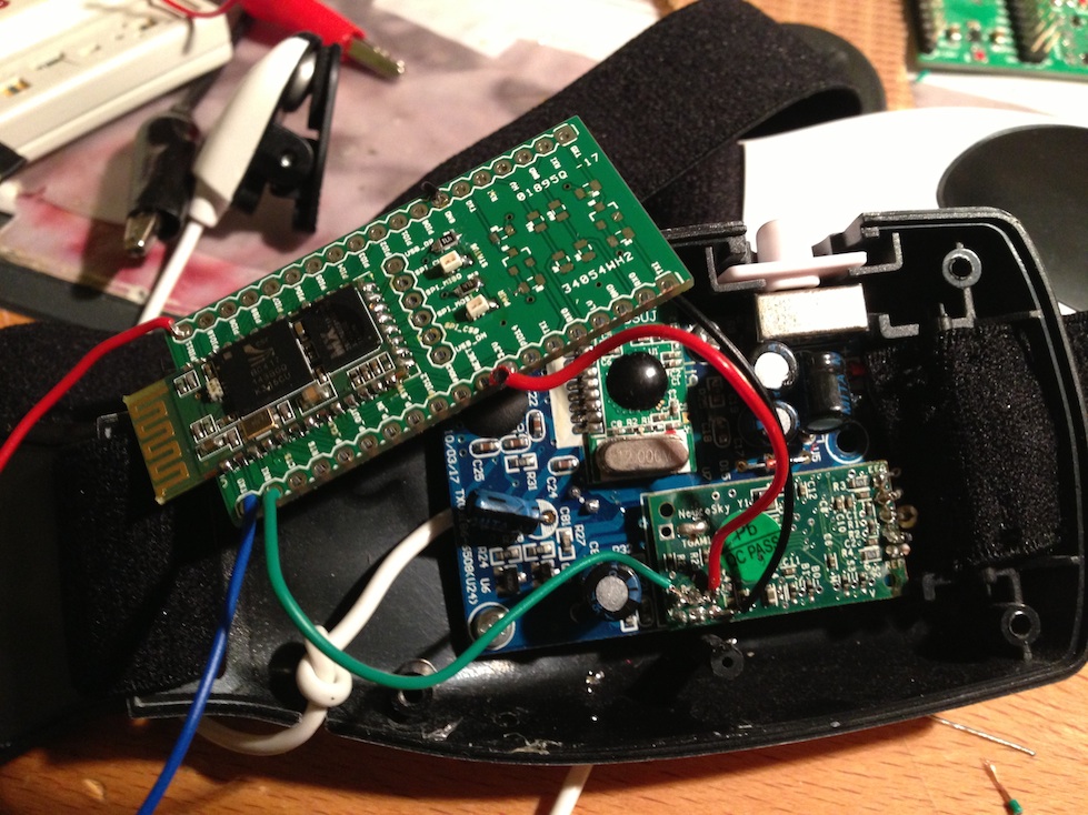
So the only part of the Mind Flex you need is the headset. Following the guide in the blog mentioned above, you’ll find the RX pin as described, which can deliver the data from the neuro chip to an Arduino. Basically all you have to do is solder a stranded wire to it, which is then connected to the Arduino’s TX pin. After installing the Brain Library and the corresponding example sketch, the Arduino receives data from the headset.
The wired connection was good enough for the first experiments. However, the headset was supposed to be connected to the Arduino wirelessly. The simplest solution turned out to be a serial Bluetooth bridge. This bridge can be built with the BTM400_6B Bluetooth module HC-05. The module is relatively inexpensive. You need 2 modules. The first one runs in slave mode and the other one in master mode. You can find a detailed description of how to configure slave mode here. You also need the hardware address of the slave module. AT commands are used for configuration. The relevant commands can be found in the datasheet.
In the master module’s configuration, the slave module’s hardware address you determined has to be set using AT-BIND. After that the modules can be powered up. They then connect automatically and the bridge is up. You connect the headset’s RX pin to TX of the slave module and the master module’s TX pin to RX of the Arduino. After uploading the example program from the Brain Library, the Arduino is connected to the headset. For visualization you can use Processing and Brain Graph.
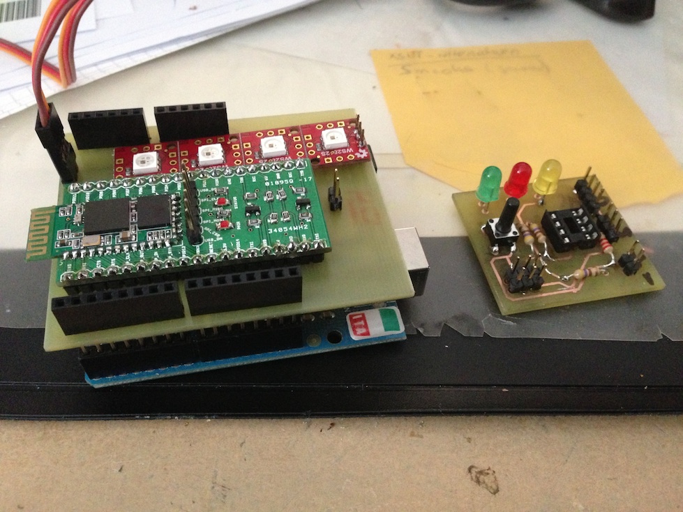
On the left, the Arduino shield with the master module. On the right, the prototype for the Autopilot.
I mounted the master module on a home-etched PCB and also added status LEDs that display the “concentration value”. With a few extra lines of code and the Arduino Servo Library I was then able to trigger the servo with my thoughts.
The project was a real success at the Mini Maker Faire in Kerkrade. Kids in particular loved this hack.
Comments