In the last part I wrote about the print head and the hotend I used. This article is unfortunately a bit shorter this time, because I’m not quite finished with (not yet happy with) the electronics setup.
Changes to the mechanics ( update to Part 3 )
While tinkering with the electronics I noticed that when the Y axis (scanner) starts moving, there is an extreme jerk in the X direction. I thought the scanner used in Part 3 was a very good fit, since it was an old scanner with two steel rods built in. Current scanners usually have only one steel rod, or none at all, as a guide. Since I still had a scanner with only one rod sitting around, I tried my luck with that one and was able to get rid of the problem. I was a little surprised, because at first I thought two rods would be more precise than just one. For building your own I recommend, for example, a Canon CanoScan LiDE 25, which you can buy used for little money on Ebay
. The following pictures show both variants once more.
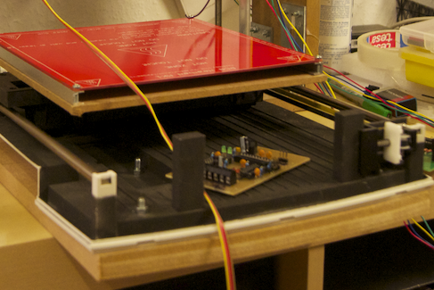
The photo shows the variant from Part 3 with two rods.
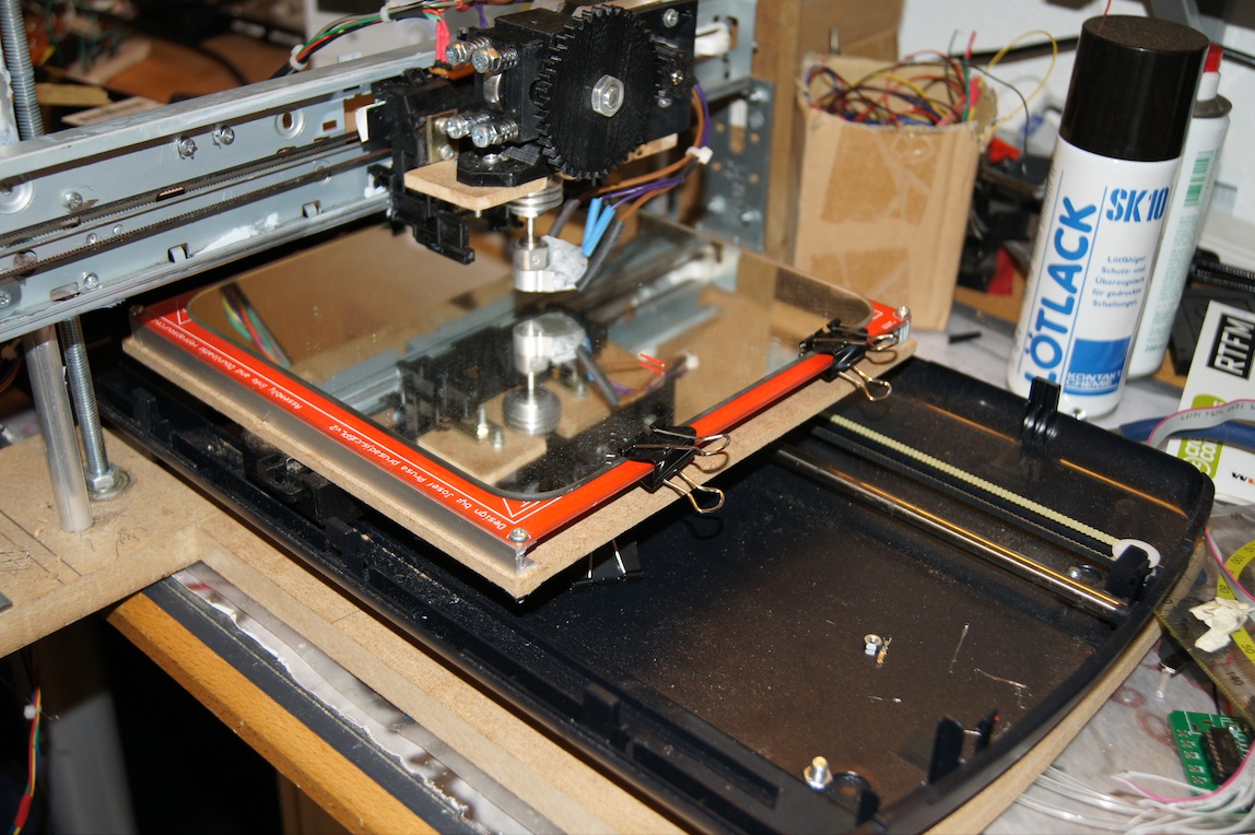
The photo shows the new variant, with a scanner that has only one steel rod built in. On the left side the carriage is guided by a plastic rail.
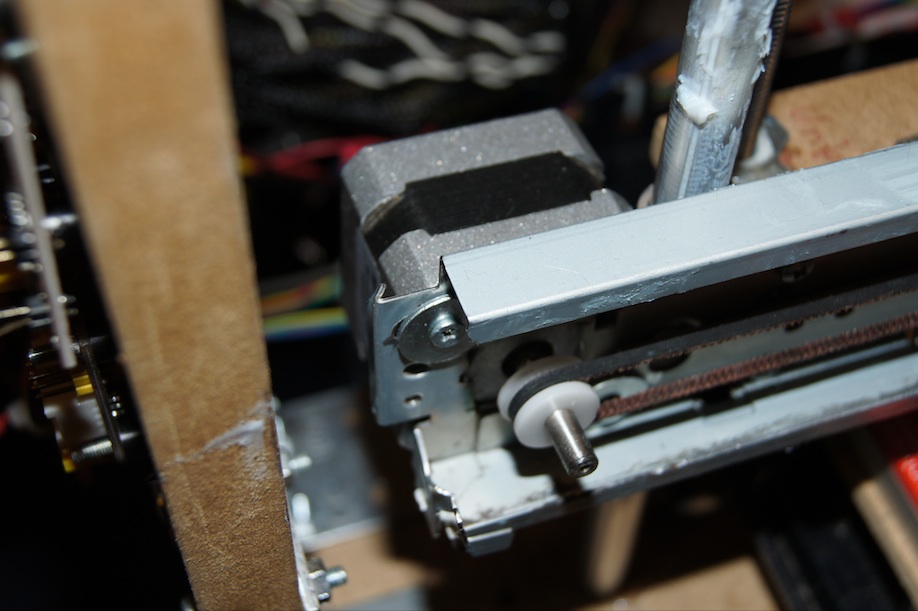
I also swapped the original stepper motor on the X axis for a NEMA 17 stepper motor , because the motor installed in Part 3 turned out to be a bit too weak to move the carriage with extruder and hotend. I’m already planning a rebuild with a gearbox here, though, so that the smaller stepper motor can be used. The NEMA 17
stepper motor is meant to serve as a stopgap here until the first working version.
Basic thoughts on control and electronics
I want to keep the electronics as simple as possible, which is why I mainly want to use components that you can buy anywhere or make yourself with modest means. All the boards that I didn’t buy but made myself are single-layer PCBs. That means they can also be built without any problems on perfboard PCBs. If there is demand, I will also offer the circuit boards in my shop.
The mainboard
As the “mainboard” I went with an Arduino. In my case I’m relying on a Seeeduino

clone). The Seeeduino has a few advantages over the regular Arduino. The Seeeduino
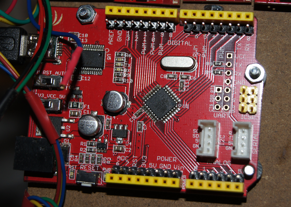
Controlling the hotend and temperature sensor
To control the hotend I used parts of the second generation of Reprap electronics. At first glance these electronics may seem outdated, but they do their job extremely well. First tests were very satisfying.
For this printer I use the PWM Driver 1.1 to drive the hotend, and the Temperature Sensor 1.1. Neither schematic should cause much trouble even for an inexperienced electronics hobbyist. So rebuilding them on perfboard is very easy. I made the PWM Driver board with my iModela mill. The Temperature Sensor I soldered onto perfboard myself as well, since configuring the mill would have taken longer than building the board by hand. You could even wire up the temperature sensor board point-to-point without any board at all.
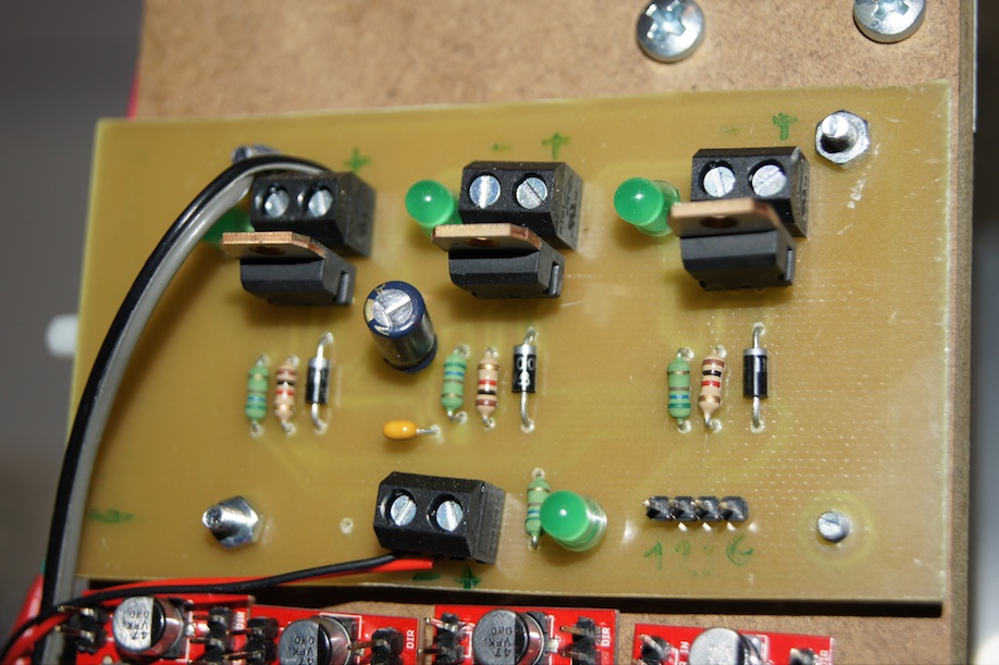
PWM Driver 1.1 – made by isolation milling
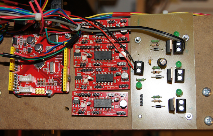
The PWM Driver board is going to be used to run the hotend, the heatbed and a fan. The PWM Driver has three outputs that can carry a voltage of up to 12 volts max. The voltage is regulated by PWM outputs of the Seeeduino. At the bottom edge of the picture you can make out four pins, three of which are used for the PWM signal while the fourth pin carries GND. At the bottom edge in the middle is the power supply (12V). The PWM Driver has three outputs, which I want to assign as already described above:
- Output 1: Hotend
- Output 2: Hotend fan
- Output 3: Heatbed
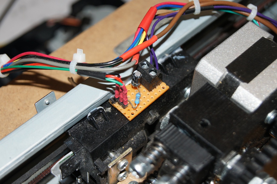
Temperature Sensor 1.1 – soldered on perfboard
On one side the temperature sensor has a connector for the thermistor built into the hotend. On the other side there are three pins, one each for an analog input on the Seeeduino, GND and the 5V supply. The exact pinout can be found in the schematic in the RepRap wiki.
Motor drivers
Here I experimented for a long time and milled numerous boards. The first idea was based on an L298-based I2C driver that I found on the web during my research. After a fair bit of fiddling I managed to build a working version of this driver. Unfortunately, the driver chip got extremely hot very quickly, which ruled it out for me. My second attempt came from the same blog. The motor driver presented there (Stepper Driver Version 4) behaves like the common drivers and is controlled via 3 pins, Enable/Step/Dir. I built a working version of this one too. At the end of the following video you can briefly see the finished driver in operation.
This motor driver is harder to make, however (even with a mill), so to allow for a simple and uncomplicated rebuild I fell back on the popular Easydriver stepper motor driver
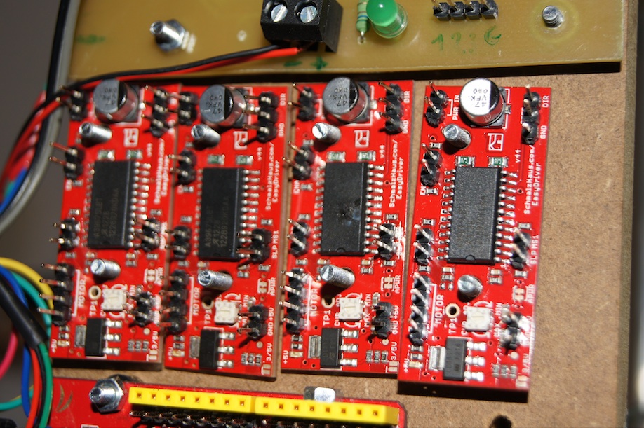
In my first attempts I wired up all the components described above. A first test of the firmware and the host software was very promising. All axes could be addressed through the host software Pronterface without any problems. The extruder and hotend pushed out material. The hotend was kept at a constant temperature. So in general everything works as planned.
Unfortunately, during these tests one of the motor drivers also went up in smoke due to a short circuit (the second from the right in the picture above). Apparently because of wiring that was too sloppy. At the moment I’m designing a shield for the Seeeduino that the motor drivers can be plugged onto. That eliminates a large part of the wiring, and the whole thing becomes tidier and hopefully “short-circuit-proof” as well.
In the next part I will write about the new wiring and about the firmware used, with the corresponding configuration, and the host software. Among other things, I will also describe there how I did a first calibration of the motors. Then there will also be another video with the first test results.
Comments