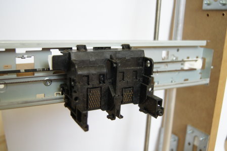
In the first part I described which parts I’m going to use to build the Repstrap from computer scrap. In this part I’ll document how I built the
X/Z plane from the printer’s linear guide and a few parts from the hardware store.
Corrections to the parts
The nuts and little plastic tubes that I glued to the printer’s linear guide in the first part turned out not to be up to the job, so I removed them again and cleaned the glue residue off the linear guide with a Dremel. A stroll through the hardware store led to the solution shown in the picture.
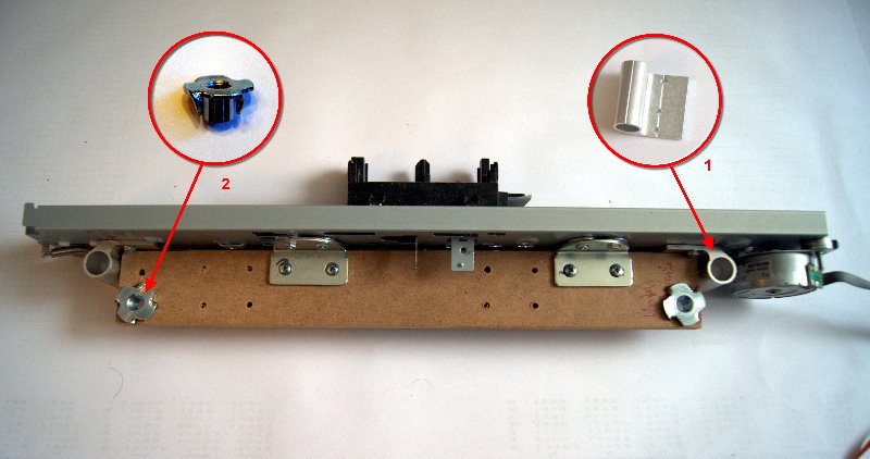
First I sawed out a piece of MDF measuring 40 x 300 x 10 mm. The width (300mm) had to be chosen so that the scanner will later fit between the threaded rods without any trouble. I then drilled holes for the threaded rods into this MDF strip. The threaded sleeves (2) (from the screw rummage box at Ikea) were inserted into these holes. To get guidance in the Z direction, I also used the aluminium parts shown in the picture (available at Bauhaus). An aluminium round rod will later run through them. The MDF part was screwed to the sheet metal of the linear guide with angle brackets. The following picture shows the scanner (Y axis) and the printer’s linear guide (X axis) once more in detail. In the picture you can see that the scanner’s linear guide fits exactly between the threaded sleeves (1). Since the threaded rods will later be supported by ball bearings in an MDF board underneath the scanner, I had to remove a bit of plastic (2) from the scanner with the Dremel.
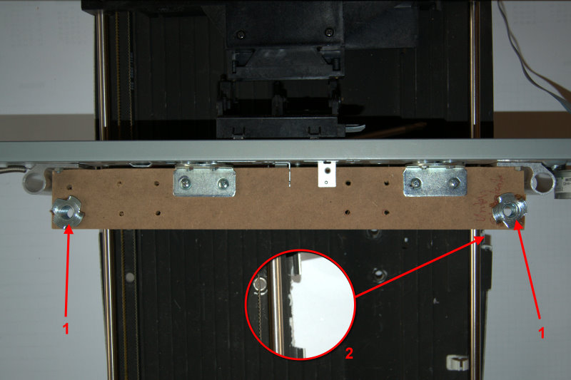
That completed the improvements to the parts, and I could move on to building the frame for the Z axis.
Frame for the Z axis
To build the frame for the Z guide I used MDF with the following dimensions:
- 2 x MDF 100 x 480 x 16 mm
- 2 x MDF 100 x 350 x 16 mm
The frame was screwed together with metal angle brackets from the hardware store. I had to make sure there was enough room at the front for the threaded rods and the guide rods. In the picture you can see that I used shorter brackets at the front for this reason.
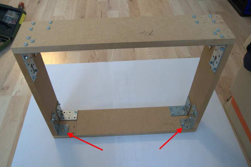
Next I prepared the holes for the ball bearings that are meant to support the threaded rods. I made the holes with a hole saw. Afterwards I enlarged the holes a little with the Dremel so that the ball bearings could be fitted in exactly. The ball bearings were glued into the holes with hot glue and superglue.
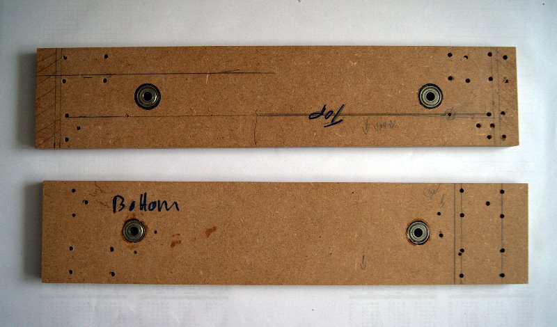
In addition, 2 more holes were drilled for mounting the aluminium rods.
Final assembly
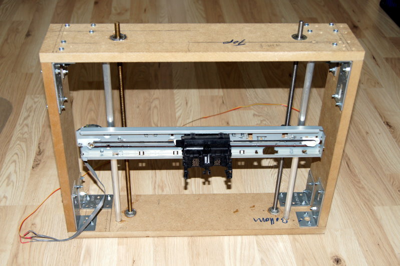
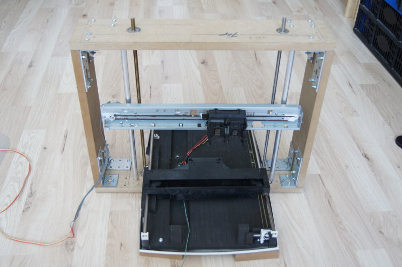
Finally, all the parts could be assembled. The threaded rods are fixed at the bottom with 2 nuts. At the top the threaded rods are supported loosely. To save time, the X carrier was screwed onto the threaded rods with the help of a cordless screwdriver. The finished assembly can be seen in the following picture.
In the next part I’ll describe finishing the mechanics and installing the motor for the Z axis.
Comments